Table of Contents
Advertisement
Installation, Operation, and Maintenance
Blower Coil Air Handler
Single Zone Air Handler, 400 to 4000 CFM
Models BCHE, BCVE and later design sequence
Only qualified personnel should install and service the equipment. The installation, starting up, and servicing of heating, ventilating, and air-conditioning equipment
can be hazardous and requires specific knowledge and training. Improperly installed, adjusted or altered equipment by an unqualified person could result in death or
serious injury. When working on the equipment, observe all precautions in the literature and on the tags, stickers, and labels that are attached to the equipment.
June 2022
SAFETY WARNING
BCX-SVX002A-EN
Advertisement
Table of Contents
Troubleshooting

Related Manuals for Trane BCVE


Summarization of Contents
Installation, Operation, and Maintenance
Blower Coil Air Handler
Details on blower coil air handler units for single zone applications.
Models BCHE, BCVE and later design sequence
Identifies specific blower coil unit models covered in the manual.
Introduction
Warnings, Cautions, and Notices
Defines and explains safety advisories used throughout the manual.
Follow EHS Policies!
Instructs personnel to follow Environmental, Health, and Safety policies.
Model Number Description
Digit 1, 2, 3, 4 — Unit Model
Defines codes for BCHE (Horizontal) and BCVE (Vertical) unit models.
Digit 5, 6, 7 — Unit Size
Specifies unit size codes from 12 (1 Ton) to 120 (10 Ton).
General Information
Horizontal blower coil (BCHE model)
Provides general information and diagram for horizontal blower coil units.
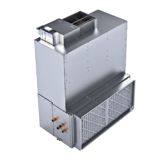
Vertical blower coil BCVE size 24-60
Illustrates the vertical blower coil unit and its components.
Pre-Installation
Receiving and Handling
Instructions for inspecting, handling, and receiving unit shipments.
Site Preparation
Details required site preparation, including weight support and space.
Dimensions and Weights
Service Clearances
Provides recommended service clearance diagrams for unit installation.
Table 1. Service requirements (inches)
Table detailing service clearance dimensions (A and B) by unit size.
Dimensions and Weights
Horizontal Blower Coil
Diagram and details for the BCHE horizontal blower coil unit.
Table 2. BCHE horizontal blower coil dimensions (inches) and weights (lb)
Table of dimensions and weights for BCHE horizontal blower coils.
Dimensions and Weights
Vertical Blower Coil
Diagram for BCVE vertical blower coil, size 24-60.
Table 3. BCVE 24 to 60 vertical blower coil dimensions (inch) and weights (lb)
Table of dimensions and weights for BCVE 24-60 vertical units.
Options
Angle Filter and Mixing Box
Details on angle filter and mixing box options and their dimensions.
Bottom/Top Access Filter Box
Diagram for bottom/top access filter box option.
Return and Discharge Attenuators
Diagrams for return and discharge attenuator options.
Electric Heat
Figure 18. BCHE/BCVE blower coils with electric heat section
Diagrams showing electric heat sections for BCHE/BCVE units.
Table 11. BCHE/BCVE blower coils with electric heat section dimensions (inches) and weights (lb)
Table of dimensions and weights for electric heat sections.
Coil Connections
Table 15. BCHE hydronic coil connection sizes, OD (inches)
Table of hydronic coil connection sizes for BCHE units.
Table 17. BCHE DX coil connection sizes, OD (inches) (continued)
Continuation of BCHE DX coil connection size table.
Sample Piping Schematics
Illustrates typical piping schematics for 2-way valves.
Dimensions and Weights
Valve and Actuator Operation
Explains operation of valves and actuators, excluding specific Cv values.
Valve Stroke Time
Provides stroke time data for various valve selections.
Installation Mechanical
Lifting and Rigging
Safety warnings and procedures for lifting and rigging the unit.
General Lifting Considerations
Guidelines for estimating center of gravity and using proper rigging methods.
Figure 31. Ceiling mounted horizontal unit
Diagram showing ceiling mounting of horizontal units with suspension rods.
Installation Mechanical
Figure 32. Add nut and flat washers to threaded rod
Illustrates attaching nuts and washers to threaded rods for mounting.
Vertical Unit (Model BCVE) Installation
Procedures for installing vertical BCVE units on the floor.
Accessory Installation — Mix Box, Angle Filter, Bottom Access Filter, and Attenuators
Instructions for installing various unit accessories.
Installation Mechanical
Figure 36. Mix box install
Diagram illustrating the installation of a mix box accessory.
Installation Mechanical
Duct Connections
Standards and recommendations for connecting ducts to the unit.
Installation Mechanical
Condensate Drain Connections
Guidelines for sizing and installing condensate drain lines and traps.
Figure 42. BCXE drain pan removal
Diagram showing the removal process for the BCXE drain pan.
Piping and Connections
Connection Leaks!
Notice regarding potential leaks at coil headers and connection points.
General Recommendations
Recommendations for proper installation, piping, and trapping of coils.
Drain Pan Trapping (Models BCHE/BCVE)
Instructions for drain pan trapping, especially for negative pressure applications.
Piping and Connections
Water Coil Piping
Information on water coil self-venting and combinations for minimum velocity.
Refrigerant Coil Piping
Guidance on refrigerant coil piping and split-system component arrangement.
Piping and Connections
Liquid Lines
Details on liquid line sizing, routing, and insulation.
Components
Lists necessary liquid-line refrigerant components and their sequence.
Piping and Connections
Suction Lines
Guidance on suction line sizing, routing, and insulation.
Piping and Connections
R-410A Refrigerant under Higher Pressure than R-22!
Warning about R-410A refrigerant's higher pressure and required equipment.
Expansion Valves
Information on expansion valves for metering refrigerant into evaporator coils.
Piping and Connections
Field-Installed Evaporator Piping
Illustrates typical piping for single-circuit evaporator coils.
Installation - Controls
Control Options
Lists available control options: CSTI, Thermostat, and UC400-B.
Customer Supplied Terminal Interface (CSTI)
Details the CSTI interface for field-supplied thermostats or controllers.
Cooling
Describes how the CSTI changeover function provides cooling.
Installation - Controls
Heating
Explains how the CSTI changeover function provides heating.
Installation - Controls
Thermostat
Information on wall-mounted, field-installed thermostats and their control.
Figure 55. Thermostat wiring diagram
Illustrates wiring diagrams for various thermostat system configurations.
Installation - Controls
Communication Wire Specifications
Details specifications for BACnet MS/TP link wiring.
Tracer® UC400-B Controller
Overview of the UC400-B controller for VAV control applications.
Installation - Controls
MAC Address
Explanation of MAC Address requirements for BACnet operation.
BACnet Device ID
Explanation of BACnet Device ID requirements for network operation.
Installation - Controls
BACnet networks with a Tracer® SC system controller
How Device ID is soft set with a Tracer SC system controller.
Installation - Controls
WARNING Hazardous Voltage!
Warning about hazardous voltage when working with controllers.
WARNING Proper Ground Connection Required!
Emphasizes the need for proper ground connection for controllers.
Installation - Controls
Air-Fi® Wireless Communications Systems
Information on Air-Fi Wireless Communication systems and devices.
Air-Fi® Wireless Communications Interface (WCI)
Details the WCI for wireless communication between Trane SC and unit controllers.
Installation - Controls
Wireless Zone Sensors
Information on Trane wireless zone sensors and their communication.
Wired Zone Sensors
Information on using wired zone sensors with WCI.
Installation - Controls
Zone Sensor Options
Overview of available wall-mounted zone sensors for design flexibility.
Zone Sensor Installation
Steps for installing zone sensors.
Location Considerations
Guidelines for selecting optimal locations for zone sensors.
Installation - Controls
Location Considerations for Wireless Zone Sensors
Placement criteria for wireless zone sensors to ensure signal strength.
Height Requirements
Recommended mounting height requirements for zone sensors.
Installation - Controls
Figure 67. Mounting zone sensor base plate
Diagram for mounting the zone sensor base plate.
Receivers
Information on receiver installation and removal.
Installation - Controls
Zone Sensor Settings
Process for establishing communication between receiver and sensor.
Address Setting
Procedure for setting rotary address switches for receiver and sensor.
Installation - Controls
Figure 72. Receiver conducts 20 second channel scan
Diagram showing receiver channel scan process.
Associating Sensor to Receiver
Steps for associating wireless sensors with their receivers.
Installation - Controls
Sensor Operations
Details sensor operations like temporary occupancy and end-of-range values.
Receiver Power-up Sequence
Describes the sequences that occur when power is applied to the receiver.
Installation - Controls
Transmission Variables
Lists transmission time variables for wireless sensors.
Wireless Sensor Specifications
Table of technical specifications for wireless sensors.
Installation - Controls
Wireless Display Sensor (WDS)
Procedure for configuring wireless display sensors.
Installation - Controls
Displaying Setpoint or Temperature
How to configure the sensor to display temperature or setpoint.
Locking or Unlocking Settings
Procedure to lock or unlock sensor settings like setpoint or fan speed.
Installation - Controls
WDS Operating Mode
How to operate the wireless display sensor (WDS) in different modes.
Changing Room Temperature
Steps to adjust the room temperature setting on the sensor.
Installation - Controls
Changing Heating/Cooling Settings
How to change heating/cooling settings on the thermostat.
Changing Fan Settings
How to change fan settings on the thermostat.
Installation — Electrical
Unit Wiring Diagrams
Information on obtaining and using unit wiring diagrams.
Supply Power Wiring
Guidelines for proper supply power wiring, including warnings.
MCA and MOP Calculations
Calculations for Minimum Circuit Ampacity and Maximum Overcurrent Protection.
ECM Overview and Setup
Trane Electronically Commutated Motor (ECM)
Overview of Trane's ECM motor technology and its benefits.
VelociTach™ Motor Control Board
Details the VelociTach motor control board functions and features.
ECM Overview and Setup
Status Display
Explanation of the motor control board's status display and characters.
ECM Overview and Setup
Safety Requirements
Essential safety recommendations for ECM motor and control board setup.
ECM Overview and Setup
User Interface
Description of the VelociTach motor control board's on-board user interface.
ECM Overview and Setup
Table 31. Button actuation levels
Table detailing button functions and actuation levels for the user interface.
ECM Overview and Setup
Configuration Examples
Examples demonstrating how to view and change motor control board parameters.
ECM Overview and Setup
Error codes
Table listing error codes generated by the motor control board.
Adjustments
Adjustments needed for motor control board commissioning.
ECM Overview and Setup
Adjusting Variable Speed Inputs
Instructions for calibrating variable speed inputs (VSP) on the system.
ECM Overview and Setup
VSP Setup Examples
Examples illustrating VSP setup configurations for optimal performance.
ECM Overview and Setup
Adjusting Optional Auto-Changeover Function on CSTI Units
How to adjust the auto-changeover function on CSTI units.
ECM Overview and Setup
Motor Control Board Settings
Details motor control board functions and unit-specific settings.
ECM Overview and Setup
Table 33. Configuration settings of the motor control board (for reference only)
Table of motor control board configuration settings and their descriptions.
ECM Overview and Setup
Fan Speed Response Verification
Procedure to verify fan speed response after commissioning.
Start-Up
Pre-Startup Checklist
Checklist to verify installation procedures before unit startup.
General Checklist
A general checklist to ensure all installation steps are complete.
Start-Up
Thermostat
Information on thermostat configuration and operation.
Thermostat Operation
How the thermostat operates in auto fan mode and other modes.
Start-Up
Button Functions
Description of thermostat buttons and their functions.
Operating Modes
Explanation of the four possible operating modes for the thermostat.
Start-Up
Tracer® UC400-B Controller
Overview of the Tracer UC400-B controller for VAV control.
Analog Sensors
Information on thermistor sensors used for temperature measurements.
Start-Up
Zone Sensor
Details zone sensor inputs and setpoint adjustments.
Fan Switch
How the zone sensor fan switch controls fan operation.
Start-Up
UC400-B Stand-Alone Operation
Procedure for operating the UC400-B controller in stand-alone mode.
UC400-B Operation
Overview of controller operation, including fan modes.
Start-Up
Occupancy Modes
Explanation of different occupancy modes: Occupied, Unoccupied, Standby, Bypass.
Timed Override Control
How to use timed override buttons for temporary occupancy.
Start-Up
Zone Temperature Control
Methods for controlling zone temperature: Cascade, Simplified, Discharge Air.
Discharge Air Tempering
Function to temper discharge air during cooling mode.
Start-Up
Water Temperature Sampling Function
Function for sampling entering water temperature for hydronic systems.
Fan Operation
Details fan operation modes: continuous, AUTO, and manual.
Start-Up
Exhaust Control
How exhaust control is achieved via binary output and its coordination.
Valve Operation
Explains controller support for modulating and two-position valves.
Start-Up
Economizing (Free Cooling)
How the controller supports economizing or free cooling.
Electric Heat Operation
Details operation of staged and modulating electric heat.
Start-Up
Dehumidification Operation
Conditions under which the controller supports space dehumidification.
Unit Protection Strategies
Strategies to protect the unit or building from damage.
Smart Reset
Automatic restart procedure for units locked out by diagnostics.
Start-Up
Freeze Avoidance
Protection against freezing during low ambient temperatures when fan is OFF.
Freeze Protection (Discharge Air Temperature Low Limit)
Protection against freezing by monitoring discharge air temperature.
Routine Maintenance
Hazardous Service Procedures!
Safety precautions for technicians performing maintenance.
Rotating Components!
Warning about hazards associated with rotating components during servicing.
Routine Maintenance
Fans
Information on inspecting and cleaning fan sections.
Fan Motors
Periodic inspection of fan motors for vibration or temperature.
Routine Maintenance
Coils
General recommendations for keeping coils clean for maximum performance.
Water Coils
Safety warnings and procedures for cleaning water coils.
Routine Maintenance
Refrigerant Coils
Safety warnings and procedures for cleaning refrigerant coils.
Coil Winterization
Procedures for water coil winterization to prevent freeze-up.
Routine Maintenance
Cleaning Non-Porous Surfaces
Procedures for cleaning non-porous insulating surfaces.
Cleaning Porous Surfaces
Procedures for cleaning porous insulating surfaces.
Drain Pans
Safety warnings and procedures for cleaning condensate drain pans.
Diagnostics and Troubleshooting
Hazardous Service Procedures!
Safety precautions for troubleshooting procedures.
Table 43. Troubleshooting recommendations
Table of common symptoms, probable causes, and recommended actions.
Diagnostics and Troubleshooting
Receiver Diagnostics
Explanation of receiver LED states and their diagnostic meanings.
Diagnostics and Troubleshooting
Sensor Diagnostics
Explanation of sensor LED states and error codes shown on the WDS.
Testing Signal Strength
Procedure to test signal strength between sensors and receivers.
Diagnostics and Troubleshooting
Testing Battery Status
Procedure to test battery status for wireless sensors and receivers.
Diagnostics and Troubleshooting
24 V Power Status Indicator
Indicator for normal 24V power status on the receiver.
Check Signal Strength on a Site
Steps to check signal strength on-site for wireless systems.
Diagnostics and Troubleshooting
Manual Association
Procedure for manually associating receivers and sensors.
Disassociation
Conditions and procedures for disassociating sensors from receivers.
Diagnostics and Troubleshooting
Servicing and Testing Tools
Tools and procedures for servicing and testing wireless sensor systems.
Procedure for Testing Zone Sensor
Steps to test zone sensors when they are not working as expected.
Diagnostics and Troubleshooting
Measuring Output Resistance
Procedure to measure receiver output resistance for diagnostics.
Cleaning the Sensor
Instructions for cleaning sensors without causing damage.
Diagnostics and Troubleshooting
Tracer® UC400-B Controller
Description of LED activity for the Tracer UC400-B controller.
Diagnostics and Troubleshooting
Overriding Outputs
How to safely override controller outputs for testing or commissioning.
Diagnostics
Explanation of diagnostic messages and their effect on controller operation.
Diagnostics and Troubleshooting
Table 54. Diagnostics generated by UC400-B controller
Table listing UC400-B controller diagnostics, causes, consequences, and types.
Diagnostics and Troubleshooting
Fans with UC400-B Controller
Troubleshooting fan issues when using UC400-B controller.
Diagnostics and Troubleshooting
Valves with UC400-B Controller
Troubleshooting valve issues when using UC400-B controller.
Diagnostics and Troubleshooting
DX Coils or Electric Heat with UC400-B Controller
Troubleshooting DX coils or electric heat with UC400-B controller.
Outdoor Air Dampers with UC400-B Controller
Troubleshooting outdoor air damper issues with UC400-B controller.
Diagnostics and Troubleshooting
ECM Motors
General information and warnings related to ECM motors.
General Information
Overview of VelociTach motor control board monitoring and speed requests.
Diagnostics and Troubleshooting
Troubleshooting Tips
Tips for troubleshooting VelociTach motor control board and ECM motor issues.
Table 61. Motor does not spin, spins too slowly
Troubleshooting table for motor spin issues.
Diagnostics and Troubleshooting
Replacing ECM Components
Guidelines and warnings for replacing ECM motor components.
Diagnostics and Troubleshooting
Replacement Checklist
Checklist to ensure proper replacement of ECM components.
Circuit Module Replacement
Procedure for replacing circuit modules on the control board.
Diagnostics and Troubleshooting
Application Notes
Notes on ECM motor differences and application considerations.
RPM Mode
Explanation of RPM mode operation for ECM motors.
Diagnostics and Troubleshooting
Troubleshooting Other Unit Functions
How ECM operation may interact with other system components.
Wiring Diagrams
Table 63. Wiring diagram matrix
Matrix listing available wiring diagrams by number and description.
Layout and Control Box Diagrams
Figure 109. Left-hand control box with motor, electric heat, condensate overflow, low-limit switch, discharge air temperature, and angle filter/ mixing box actuator
Diagram of the left-hand control box and its components.
Layout and Control Box Diagrams
Figure 110. Right-hand control box with motor, condensate overflow, low-limit switch, and discharge air temperature
Diagram of the right-hand control box and its components.
Layout and Control Box Diagrams
Figure 111. Size 24 to 60 BCVE unit with condensate overflow, low-limit switch, and discharge air temp
Diagram of BCVE 24-60 unit showing key components in the control box.
Layout and Control Box Diagrams
Figure 112. Control box for Tracer® UC400-B controller
Diagram of the control box for the Tracer UC400-B controller.
Figure 113. Control box for CSTI with 2-stage EH and DX coil
Diagram of the control box for CSTI with 2-stage EH and DX coil.
Need help?
Do you have a question about the BCVE and is the answer not in the manual?
Questions and answers