Advertisement
Quick Links
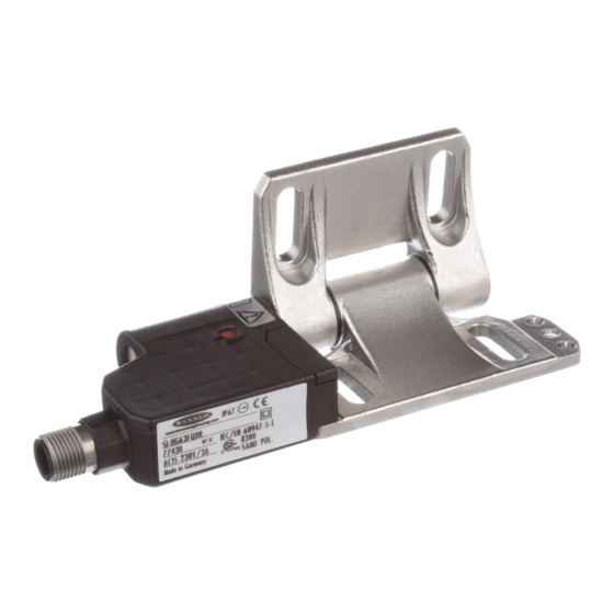
SI-HG(Z)63 Hinge Wing Safety Interlock Switch
Instruction Manual
The SI-HG(Z)63 Hinge Wing Safety Interlock Switch attaches with a load-bearing hinge.
Models
Model
Construction
SI-HG63FQDR
Stainless Steel
SI-HGZ63FQDR
Zinc Die-cast
SI-HG63F5MR-W
Stainless Steel
SI-HG63FQDL
Stainless Steel
SI-HGZ63FQDL
Zinc Die-cast
SI-HG63F5ML-W
Stainless Steel
SI-HG63FQDRR
Stainless Steel
SI-HGZ63FQDRR
Zinc Die-cast
SI-HG63F5MRR-W
Stainless Steel
SI-HG63F5MLR-W
Stainless Steel
SI-HG63F5MB-W
Stainless Steel
SI-HG63A
Stainless Steel
SI-HGZ63A
Zinc Die-cast
A complete safety system is composed of two SI-HG(Z)63 switches per gate/guard (SI-HG63F5MB-W is two switches so only one is
needed for a complete system), cables (for QD models), and a safety monitoring device.
Original Document
129465 Rev. G
•
Safety switching point is repositionable
•
Switch components are protected from mechanical impact for superior performance to actuator-
activated safety switches (IP67 or IP69 rated)
•
Hinge operates to a full 270° range of motion; safety switching point (guard-closed position) is
adjustable over the full 0° to 270° operating range
•
Stainless steel hinge supports a load of 1800 N (180 Kg). Zinc die-cast hinge supports a load of
1200 N (120 Kg).
•
When properly interfaced or used with an appropriate controller, two SI-HG(Z)63 switches on an
individual gate or guard can achieve safety category 4, per ISO 13849-1
Housing Style
Inline QD - With QD facing down, switch is mounted on right side of hinge
Inline Cable - With cable exiting down, switch is mounted on right side of hinge, IP69 protection class rating
Inline QD - With QD facing down, switch is mounted on left side of hinge
Inline Cable - With cable exiting down, switch is mounted on left side of hinge, IP69 protection class rating
Right-Angle QD - With switch body down, switch is mounted on right of hinge
Right-Angle Cable - With switch body down, switch is mounted on right side of hinge, IP69 protection class rating
Right-Angle Cable - With switch body down, switch is mounted on left side of hinge, IP69 protection class rating
Inline Cables - With cables exiting up and down, switches are mounted on both sides of hinge, IP69 protection
class rating
Blank Hinge; same mechanical as switch minus switch component
16 March 2022
129465
Advertisement

Related Manuals for Banner SI-HGZ63FQDL


Summarization of Contents
Installation Requirements and Guidelines
Pass-through Hazards and Perimeter Guarding
Addresses specific safety concerns for applications involving passage through safeguards and related risks.
Mechanical Installation Procedures
Details the physical mounting procedures and considerations for the hinge switch component.
Mechanical Setup and Adjustment
Setting the Switch Point
Procedure for setting the initial switching point of the safety interlock switch.
Fine-Adjusting the Switch Point
Instructions for fine-tuning the switch point to compensate for installation deviations.
Repositioning the Hinge or Switch
Steps for relocating the switch point or repositioning the hinge for different configurations.
Electrical Installation and Connectivity
Connection to a Machine
Details on how to connect the safety interlock switch to the machine's control system.
Monitoring Series-Connected Switches
Guidance on monitoring safety switches connected in series for system integrity.
Product Specifications and Dimensions
Technical Specifications
Provides detailed electrical, mechanical, and environmental specifications for the switch.
Model Dimensions
Illustrates the physical dimensions for various SI-HG(Z)63 models.
Guard Opening Calculation
Method for calculating guard opening size relative to switching point for safety.
Accessories and Related Products
Safety Monitoring Devices
Lists compatible safety monitoring devices required for switch functionality.
Cordsets for Connection
Details available cordsets for connecting the safety interlock switch.
Replacement Accessory Kit
Information on kits available for replacing parts like washers, plugs, and screws.
Product Support and Maintenance
Checkout Procedures
Essential steps for testing switch functionality after installation or replacement.
Repair and Return Policy
Guidance on product repairs, warranty, and contacting support for issues.
Standards, Regulations, and Warranty
Applicable Standards and Regulations
Lists relevant US, International, and European standards for safety machinery.
EU/UK Declaration of Conformity
Declaration confirming product conformity with EU/UK directives and safety requirements.
Banner Engineering Warranty
Details the limited warranty terms for Banner Engineering products.
Need help?
Do you have a question about the SI-HGZ63FQDL and is the answer not in the manual?
Questions and answers