
Related Manuals for Banner SI-RFPT-HP5


Summarization of Contents
1 Product Overview
1.1 Models
Lists available SI-RF Safety Switch models with their configurations and connectors.
1.2 Important... Read this before proceeding!
Emphasizes user responsibility for safety laws, rules, and understanding instructions.
1.3 EU Declaration of Conformity (DoC)
Declares conformity with EU directives and essential health and safety requirements.
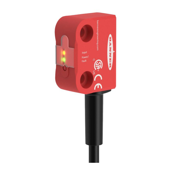
1.4 Overview
Explains the SI-RF Safety Switch's function for guard monitoring and interlocking applications.
2 Configuration Instructions
2.1 Safety Code for Operation
Explains the three coding levels (Low, High, Unique) for actuator identification.
2.2 Teach the Safety Code
Provides a step-by-step guide for teaching the actuator code to the safety switch.
3 Installation Instructions
3.1 Installation Requirements
Outlines general requirements for installing interlocked gates and guards for safeguarding.
3.2 Pass-through hazards and Perimeter Guarding
Discusses how to eliminate or reduce pass-through hazards and perimeter guarding risks.
3.3 Mechanical Installation
Details how to securely mount the safety switch and actuator to prevent tampering.
3.4 Sensing Distance
Explains switching distances and detection range for the sensor and actuators.
3.5 Resetting the Inputs
Explains the local reset function for confirming safety outputs after guard closure.
3.6 Auxiliary Output/Information
Describes the PNP diagnostic output for non-safety related status information.
3.7 In-Series Diagnostic Information
Introduces the In-Series Diagnostic (ISD) interface for sensor information.
3.8 Electrical Installation
Details electrical connection requirements and safety considerations.
3.8.1 Protective Stop (Safety Stop) Circuits
Explains protective stop circuits for orderly cessation of motion and power removal.
3.8.2 Output Signal Switching Devices (OSSDs) and External Device Monitoring (EDM)
Details how OSSD outputs interact with machine control and the need for EDM.
3.8.3 Wiring for Single PNP (SI-RFP)
Describes the 5-conductor wiring scheme for a single PNP SI-RFP switch.
3.8.4 Wiring for a Single 8-Conductor Sensor
Details the wiring for a single 8-conductor sensor SI-RF Safety Switch.
3.8.5 Wire the Switch in Series
Provides steps for monitoring multiple guards using a series connection of SI-RF Safety Switches.
3.8.6 Wire the Switch in Series Using the Quick Disconnect
Explains connecting switches in series using special t-adapters and quick disconnects.
4 Specifications
4.1 Dimensions
Lists all physical dimensions for the SI-RF Safety Switch and actuator.
5 Accessories
5.1 Cordsets
Details various M12/Euro-style cordsets, including pinouts and lengths.
5.2 Adapters and Other Accessories
Lists adapters and other accessories like T-adapters and termination plugs.
5.3 Safety Controllers
Describes safety controllers compatible with the SI-RF Safety Switch system.
5.4 Universal (Input) Safety Modules
Explains safety modules for external manual reset or device monitoring.
6 Product Support and Maintenance
6.1 Maintenance and Service
Provides guidance on maintenance, service, and component exchange for the switch.
6.2 Status Indicators
Explains the meaning of LED indicators and flash codes for status and errors.
6.3 Information Available via ISD
Details the information available through the In-Series Diagnostic (ISD) interface.
6.4 Contact Us
Provides contact details for Banner Engineering Corp. headquarters.
6.5 Banner Engineering Corp. Limited Warranty
Outlines the manufacturer's warranty terms and conditions for the product.
Need help?
Do you have a question about the SI-RFPT-HP5 and is the answer not in the manual?
Questions and answers