Table of Contents
Advertisement
Quick Links
Rope Pull Emergency Stop Switches
Instruction Manual
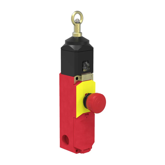
RP-LS42F-xxL and xxLF Series 42 mm Latching Switches with Rope/Cable Actuators
Models
75 m (246.1 ft) / 300 N
RP-LS42F-75L
RP-LS42F-75LF
Run
13
14
21
22
33
34
41
42
Note: This symbol
contact (IEC 60947-5-1) is used in the switching diagram
to identify the point in actuator travel where the normally-
closed safety contact is fully open.
Important... Read this before proceeding!
The user is responsible for satisfying all local, state, and national laws, rules, codes, and regulations relating to the use of this
product and its application. Banner Engineering Corp. has made every effort to provide complete application, installation, operation,
and maintenance instructions. Please contact a Banner Applications Engineer with any questions regarding this product.
The user is responsible for making sure that all machine operators, maintenance personnel, electricians, and supervisors are
thoroughly familiar with and understand all instructions regarding the installation, maintenance, and use of this product, and with the
machinery it controls. The user and any personnel involved with the installation and use of this product must be thoroughly familiar
Original Document
67709 Rev. C
•
Positive-opening safety contacts (IEC 60947-5-1), not dependent upon springs
•
Both safety contacts latch open when rope is pulled, broken, or if tension is reduced;
requires manual reset (IEC 60947-5-5)
•
Compliant with ANSI B11.19, NFPA 79, IEC/EN 60204-1 and ISO 13850 Emergency Stop
requirements
•
Heavy-duty thermoplastic housing (polyamide), rated IP67, suitable for demanding industrial
environments; insulated device
•
Innovative quick-connect design provides quick, easy rope fixing and tensioning on RP-
LS42F-..LF models
•
Rope spans of 25 m (82 ft), 37.5 m (125 ft), and 75 m (245 ft), depending on model
•
Monitoring contacts operate opposite the safety contacts, for monitoring by another device
or interfaced with EZ-LIGHT
•
Tension indicator window indicates proper rope tension for operation or safety contacts
latched open (the rope pull or the E-stop button is actuated)
Maximum Rope Length / Force
38 m (124.7 ft) / 175 N
RP-LS42F-38L
RP-LS42F-38LF
Figure 1. Contact State
Pull / Break
13
21
33
41
for a positive-opening safety
4 November 2021
®
indicators
25 m (82.0 ft) / 100 N
RP-LS42F-25L
RP-LS42F-25LF
+5 mm
+4.3 mm
+3.5 mm
14
22
0 mm
34
42
-3.5 mm
-4.3 mm
-5 mm
Contacts:
Rope
E-Stop
Connection
Button
Ring
No
Turnbuckle
No
Figure 2. Switching Diagram
100N / 175N / 300N
Latch
80N / 140N / 240N
Latch
60N / 105N / 180N
Operating point ± 0.5 mm
Actuating force ± 15%
Open
Closed
Transition
67709
Advertisement
Table of Contents

Subscribe to Our Youtube Channel
Related Manuals for Banner RP-LS42F L Series


Summary of Contents for Banner RP-LS42F L Series
- Page 1 The user is responsible for satisfying all local, state, and national laws, rules, codes, and regulations relating to the use of this product and its application. Banner Engineering Corp. has made every effort to provide complete application, installation, operation, and maintenance instructions. Please contact a Banner Applications Engineer with any questions regarding this product.
-
Page 2: Mechanical Installation
Rope Pull Emergency Stop Switches with all applicable standards, some of which are listed within the specifications. Banner Engineering Corp. makes no claim regarding a specific recommendation of any organization, the accuracy or effectiveness of any information provided, or the appropriateness of the provided information for a specific application. -
Page 3: Installation Procedure
WARNING: • Properly install the device • Failure to follow the installation instructions can result in ineffective or non-operation of the Banner device, which could create an unsafe condition resulting in serious injury or death. • Follow all installation instructions. - Page 4 Rope Pull Emergency Stop Switches Figure 4. Individual Tension Springs Figure 5. Tension Spring Assembly Spring Breakage Protection Cable RP-LS42F-25xx/-38xx RP-LS42F-75xx RP-LS42F-25xx/-38xx RP-LS42F-75xx Tensioning Tensioning Spring RPA-S6-1 RPA-S4-1 RPA-S5-1 RPA-S3-1 Spring Assembly L min 185 mm 201 mm L min 362 mm 465 mm 300 mm...
- Page 5 Rope Pull Emergency Stop Switches a) Strip away a minimum of 100 mm to 150 mm (4 in to 6 in) of the red rope sheathing. Additional length of red sheathing maybe required to be removed depending on total slack in the rope. b) Using a 4 mm hex wrench, loosen the set screw on the switch fitting.
-
Page 6: Electrical Installation
4. Make sure that all wires are securely held and will not short to adjacent terminals (that is, no bent or stray strands of wire). 5. Snap the access cover shut (a click will be heard). Banner recommends securing the access cover with the supplied #2-28 ×... - Page 7 Rope Pull Emergency Stop Switches Figure 13. Safety Contacts at 21/22 and 41/42 CH2 (N.C.) CH1 (N.C.) To ensure the highest level of reliability (Control Reliable or Category 4, for example), wire the positively-driven safety contacts (terminals 21/22 and 41/42) in a dual channel hookup to a safety module (for example, ES-FA-9AA), safety controller (for example, XS/SC26 or SC10-2roe), or the safety related part of the machine control that complies with the required level of safety performance.
-
Page 8: Specifications
Repairs Contact Banner Engineering for troubleshooting of this device. Do not attempt any repairs to this Banner device; it contains no field-replaceable parts or components. If the device, device part, or device component is determined to be defective by a Banner Applications Engineer, they will advise you of Banner's RMA (Return Merchandise Authorization) procedure. -
Page 9: Cable Gland
Rope Pull Emergency Stop Switches Dimensions Figure 14. RP-LS42F..L Models Figure 15. RP-LS42F-xxLF Models 317 mm (12.48") 224.0 mm 265 mm (8.82") (10.43") 124.0 mm (4.88") 45.0 mm 5.0 mm 30.0 mm (1.77") (0.20") (1.18") 42.5 mm 78.3 mm 78.3 mm (1.67") (3.08") (3.08") - Page 10 Rope Pull Emergency Stop Switches Conduit Adapter (Supplied) Model Size Thread Conversion Dimensions Used With 25.0 mm 1/2"-14 NPT SI-GL42 Safety Interlock Switch (0.98") Internal Thread SI-LS31 Safety Interlock Switch 24.0 mm SI-LS42 Safety Interlock Switch (0.94") SI-QS-M20 ½ in-14 NPT Plastic M20 ×...
-
Page 11: International/European Standards
Rope Pull Emergency Stop Switches Model Quantity Description Tensioning Spring Used With RP-RM83 models (75 m) RPA-S3-1 Tensioning spring #3 RP-LS42 models (75 m) Tensioning spring #5 RP-RM83F-..38.. RPA-S5-1 RP-LS42 models (25 & 38 m) Model Quantity Description Tensioning Spring Used With Tensioning spring #4 with built-in eye bolt (used RP-RM83 models (75 m) -
Page 12: Eu Declaration Of Conformity (Doc)
Banner Engineering Corp. Limited Warranty Banner Engineering Corp. warrants its products to be free from defects in material and workmanship for one year following the date of shipment. Banner Engineering Corp. will repair or replace, free of charge, any product of its manufacture which, at the time it is returned to the factory, is found to have been defective during the warranty period. This warranty does not cover damage or liability for misuse, abuse, or the improper application or installation of the Banner product.
Need help?
Do you have a question about the RP-LS42F L Series and is the answer not in the manual?
Questions and answers