
Subscribe to Our Youtube Channel
Related Manuals for Banner SI-GL42 Series


Summary of Contents for Banner SI-GL42 Series
- Page 1 SI-GL42 Series Locking-Style Safety Interlock Switch Instruction Manual Original Instructions 220476 Rev. A 22 January 2021 © Banner Engineering Corp. All rights reserved 220476...
-
Page 2: Table Of Contents
SI-GL42 Series Locking-Style Safety Interlock Switch Contents 1 Product Overview ................................3 1.1 Models ......................................3 1.2 Important... Read this before proceeding! ............................5 1.3 Overview ......................................5 2 Installation Instructions ..............................6 2.1 Installation Requirements ................................6 2.2 Pass-through hazards and Perimeter Guarding .......................... -
Page 3: Product Overview
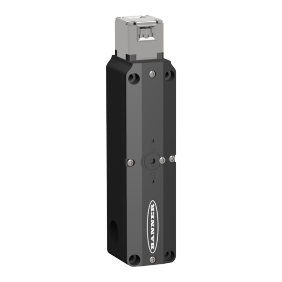
SI-GL42 Series Locking-Style Safety Interlock Switch 1 Product Overview SI-GL42 Series Locking-Style Safety Interlock Switch for interlocking and position monitoring • Positive opening safety contacts (per IEC 60947-5-1) • Contact monitors both the presence of the actuator and if it is locked into the interlock •... - Page 4 SI-GL42 Series Locking-Style Safety Interlock Switch Solenoid Interlock Body Solenoid Actuator Actuator Engaged but Not Actuator Unlocked and Monitor Actuator Engaged and Locked Model Voltage Contacts Locked Removed Contacts Actuator Contacts Actuator Contacts Actuator Contacts 24 V SI-GL42D_21-10 2 NC/1 NO...
-
Page 5: Important
1.3 Overview The SI-GL42 Series Locking-Style Safety Interlock Switch with guard locking capability can be used to monitor the position of a guard to detect its movement, opening, or removal. -
Page 6: Installation Instructions
SI-GL42 Series Locking-Style Safety Interlock Switch 2 Installation Instructions 2.1 Installation Requirements The following general requirements and considerations apply to the installation of interlocked gates and guards for the purpose of safeguarding. In addition, the user must refer to the relevant regulations and comply with all necessary requirements. -
Page 7: Pass-Through Hazards And Perimeter Guarding
SI-GL42 Series Locking-Style Safety Interlock Switch WARNING: • The hazard must be accessible only through the sensing field • Incorrect system installation could result in serious injury or death. • The installation of the SI-GL42 Interlock Switch must prevent any individual from reaching around, under, over or through the defined area and into the hazard without being detected. -
Page 8: Position The Actuator Head
SI-GL42 Series Locking-Style Safety Interlock Switch Important: It is the responsibility of the machine builder (user) to make sure the wiring/cabling is not easily manipulated by an operator to defeat the safety function(s); for example, cannot remove a switch from the system. - Page 9 SI-GL42 Series Locking-Style Safety Interlock Switch Figure 2. Actuator position Actuator fully inserted into interlock SI-GL42 Head Actuator moulded part 0.2 - 2 There is a 2 mm overtravel between the switch head and the actuator. Set the guard's stop in this overtravel region (overtravel range 0.2–2 mm).
-
Page 10: Align The Si-Qm-Smfa-2
SI-GL42 Series Locking-Style Safety Interlock Switch 2.3.3 Align the SI-QM-SMFA-2 All measurements are listed in millimeters, unless noted otherwise. Figure 4. SI-QM-SMFA-2 dimensions 1. Align and fasten SI-QM-SMFA-2 to the hinged guard as described in Install the Switch and Actuator on p. - Page 11 SI-GL42 Series Locking-Style Safety Interlock Switch CAUTION: If the escape release mechanism is used, the switch must be mounted within the hazardous area (must be accessible to an operator inside the hazardous area). The escape release mechanism should only be used to exit the hazardous area in case of a system failure. The escape release mechanism must not be accessible from outside of the hazardous area.
- Page 12 SI-GL42 Series Locking-Style Safety Interlock Switch 2. Place the mechanism onto the cover with the lock and unlock symbols toward the head of the switch and the side notches positioned over the cover mounting screws. 3. Secure into place with the included mounting screws (torque to 0.5 N·m).
-
Page 13: Access The Wiring Chamber
Perform a risk assessment to determine the means of interfacing the switch(es) with the machine control circuit. Although Banner Engineering always recommends the highest level of safety in any application, it is the responsibility of the user to safely install, operator and maintain each safety system and comply with all relevant laws and regulations. - Page 14 SI-GL42 Series Locking-Style Safety Interlock Switch Figure 8. Actuator safety contacts (circle with arrow symbol) Safety Switch #1 Safety Switch #2 Actuator Actuator Safety Safety Single gate Contact Contact or guard Locking for process control purposes Input Input Channel Channel...
- Page 15 SI-GL42 Series Locking-Style Safety Interlock Switch • A reset routing after closing the guard and returning the safety contacts to their closed position. This prevents the controlled machinery from restarting by simply reinserting the safety switch actuators. This necessary reset function is required by ANSI B11.0 and NFPA 79 machine safety standards.
-
Page 16: Operating Instructions
3 Operating Instructions 3.1 Checkout Procedures Banner Engineering highly recommends performing the checkouts as described. However, a qualified person (or team) should evaluate these generic recommendations considering their specific application and determine the appropriate frequency of checkouts. This will generally be determined by a risk assessment, such as the one contained in ANSI B11.0. -
Page 17: Specifications
SI-GL42 Series Locking-Style Safety Interlock Switch 4 Specifications Electrical Protection Class Switching Contacts Contact Rating II, totally/double insulated Insulation voltage U : 250 V (30 V with M12 QD) Impulse withstand voltage U : 2.5 kV (0.8 kV with M12 QD) - Page 18 SI-GL42 Series Locking-Style Safety Interlock Switch Figure 11. SI-QM-SMFA-2 dimensions Figure 12. SI-QM-SMFA-3 dimensions www.bannerengineering.com - Tel: + 1 888 373 6767...
- Page 19 SI-GL42 Series Locking-Style Safety Interlock Switch Figure 13. SI-QM-SSA-2 dimensions Figure 14. SI-QM-SSA-2RA dimensions www.bannerengineering.com - Tel: + 1 888 373 6767...
-
Page 20: Accessories
SI-GL42 Series Locking-Style Safety Interlock Switch 5 Accessories 5.1 Actuators and Unlock Mechanisms Minimum Approach Model Type Description Radius SI-QM-SSA-2 Straight Actuator 800 mm SI-QM-SSA-2RA Rigid Flat Mount Actuator (90° mounting) 600 mm Actuator SI-QM-SMFA-2 Fully Flexible Actuator 150 mm... -
Page 21: Safety Controllers
SI-GL42 Series Locking-Style Safety Interlock Switch Model Description ES-FA-11AA 2 Normally Open (NO) Redundant-output 7 A Contacts, plus 1 Normally Closed (NC) Auxiliary Contact 5.5 Safety Controllers Safety Controllers provide a fully configurable, software-based safety logic solution for monitoring safety and non-safety devices. -
Page 22: Product Support And Maintenance
6.3 Banner Engineering Corp. Limited Warranty Banner Engineering Corp. warrants its products to be free from defects in material and workmanship for one year following the date of shipment. Banner Engineering Corp. will repair or replace, free of charge, any product of its manufacture which, at the time it is returned to the factory, is found to have been defective during the warranty period. This warranty does not cover damage or liability for misuse, abuse, or the improper application or installation of the Banner product.
Need help?
Do you have a question about the SI-GL42 Series and is the answer not in the manual?
Questions and answers