Table of Contents
Advertisement
Quick Links
Installation and Maintenance
Instruction Manual
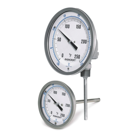
Bimetal Thermometer Modell A and E
for explosion risk areas in the European Union pursuant to Directive 2014/34/EU & for the United
Kingdom pursuant to Regulation SI 2016, No. 1107 (ATEX)
- according to ASME B40.200: 50=E#=###=ATEX or 50=ERT#=###=ATEX
- according to EN 13190:
###=A#=###=ATEX or ##=ART#=###=ATEX
IM-BiM/ATEX-EN-Rev E
09/2021
page 1 of 19
P/N 095I201-02EN
Advertisement
Table of Contents

Related Manuals for Ashcroft EI


Summary of Contents for Ashcroft EI
- Page 1 Installation and Maintenance Instruction Manual Bimetal Thermometer Modell A and E for explosion risk areas in the European Union pursuant to Directive 2014/34/EU & for the United Kingdom pursuant to Regulation SI 2016, No. 1107 (ATEX) - according to ASME B40.200: 50=E#=###=ATEX or 50=ERT#=###=ATEX...
-
Page 2: Table Of Contents
Table of Contents: General remarks ................................. 4 Purpose of this manual ............................4 Symbols ................................4 Limitation of liability ............................4 Copyright ................................4 Warranty ................................4 Manufacturer address, customer service ......................4 Safety ..................................5 General sources of danger ..........................5 Intended use .............................. - Page 3 12.1 Data sheet Bimetal Thermometer Ax / Ex ....................... 14 12.2 EU Declaration of Conformity .......................... 15 12.3 UK Declaration of conformity ........................... 17 page 3 of 19...
-
Page 4: General Remarks
1.4 Copyright These operating instructions may only be reproduced and passed on as a complete document without the special consent of the publisher. Subject to technical changes. -
Page 5: Safety
The device is to be regarded as a temperature measuring part of a plant in a potentially explosive atmosphere. The operator of this plant is obliged to carry out an ignition hazard analysis and a zone classification. -
Page 6: Signs/Safety Marking
2.5 Signs/safety marking The device is provided with a label. The label shows the type designation, measuring range, serial number, year of manufacture, certificate of approval number, filling medium, Ex marking (including X for special conditions of use) and manufacturer. - Page 7 The device-specific properties as well as the limit temperatures of the dusts and their form as a deposited layer or in the form of a surrounding dust cloud must be taken into account here.
- Page 8 Convection heat from the direct environment of the devices must also be avoided. The devices must not be operated in potentially explosive areas of a plant in which an explosive mixture of gases and dusts is present in the atmosphere.
-
Page 9: Special Operating Conditions For Safe Use In Potentially Explosive Atmospheres
The nameplate with serial number and type designation is located on the housing. The materials used for the wetted parts as well as other device-specific versions are represented by a type coding on the nameplate and can be broken down at any time with the aid of the data sheet. The marking for the hazardous areas, in the form of the description of the type of protection, the permissible ambient temperature and the deposit number, are located in the lower area of the nameplate. -
Page 10: Description Of The Components
6.3.1 Stem The stem with a diameter of 6 mm - 9.6 mm and a length of 63 mm - 1500 mm contains the bimetallic coil on the side facing away from the housing. To ensure proper functioning of the thermometer, a minimum immersion length of the stem in the media of 65 mm to 100 mm, depending on the measuring range, must be ensured. -
Page 11: Assembly/Installation
Position the thermometer housing in a straight alignment (Position “C”) Using the screws marked “A”, loosen until the joint can be turned freely through 180° on the lower part of the housing and the sensor. -
Page 12: Starting Up
9.2 Cleaning and maintenance Cleaning is carried out with a non-aggressive cleaning agent and a damp soft cloth to avoid electrostatic charging. In the same work process, care can be taken to detect possible damage to the device at an early stage. If any damage is detected, the unit should be handed over to the manufacturer's service department immediately. -
Page 13: Faults
11.2 Disposal At the end of the product life cycle, do not dispose of this product with normal household waste. Take this product to a collection point or a specialist disposal company for recycling of the components page 13 of 19... -
Page 14: Appendix
Then separate the case ring, which carries the window, from the case using a strap wrench. For device with crimped housing ring, these can be cut open with a pliers. The sealing ring and flat glass can be removed. Next, remove the pointer and dial, which are made of aluminium, everything else is made of stainless steel.. - Page 15 12.2 EU Declaration of Conformity page 15 of 19...
- Page 16 page 16 of 19...
- Page 17 12.3 UK Declaration of conformity page 17 of 19...
- Page 18 page 18 of 19...
- Page 19 page 19 of 19...
Need help?
Do you have a question about the EI and is the answer not in the manual?
Questions and answers