Table of Contents
Advertisement
Quick Links
Installation and Maintenance
Instruction Manual
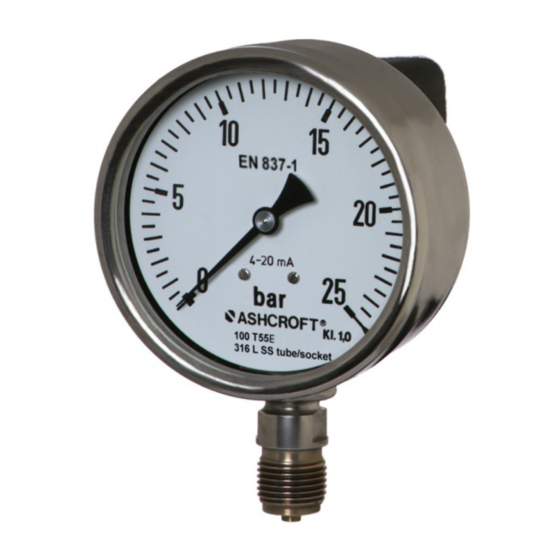
Bourdon tube pressure gauge with integrated transmitter, model T5500E
for industrial application
In the following configuration:
• 100=T5500E### bourdon tube pressure gauge with integrated transmitter
IM-T5500E-E-Rev 0 08/2014
Page 1 of 11
P/N 095I105-01EN
Advertisement
Table of Contents

Related Manuals for Ashcroft t5500e


Summary of Contents for Ashcroft t5500e
- Page 1 Installation and Maintenance Instruction Manual Bourdon tube pressure gauge with integrated transmitter, model T5500E for industrial application In the following configuration: • 100=T5500E### bourdon tube pressure gauge with integrated transmitter IM-T5500E-E-Rev 0 08/2014 Page 1 of 11 P/N 095I105-01EN...
-
Page 2: Table Of Contents
Table of contents: General remarks ................................. 3 Purpose of this Manual ............................3 Symbols ................................3 Limits of liability ..............................3 Copyright ................................3 Warranty ................................3 Manufacturer’s address, customer services......................3 Safety ..................................4 General sources of hazards ..........................4 Use in accordance with intended purpose ...................... -
Page 3: General Remarks
Removal ................................. 10 10.3 Disposal ................................. 10 Appendix ................................10 11.1 Data sheet for Bourdon tube pressure gauge with integrated transmitter T5500E ........10 11.2 CE Declaration of conformity ......................... 11 1 General remarks 1.1 Purpose of this Manual This Operating Manual contains fundamental and essential advice to be followed for the installation, operation and servicing of the device. -
Page 4: Safety
2 Safety 2.1 General sources of hazards Pressure gauges are pressurized instruments where failure can result in hazardous situations. The selection of pressure gauge should be made in accordance with the rules set out in EN 837-2. A failure resulting in injury or damage may be caused by excessive overpressure, excessive vibration or pressure pulsation, excessive instrument temperature, corrosion of the pressure containing parts, or other misuse. -
Page 5: Staff Qualifications (Target Group Assessment)
Silicone-free (for use in the automotive industry) 2.6 Safety equipment The window of model T5500E uses multi-layer safety glass. This device has internal transient and reverse power protection. 2.7 Environmental protection This device does not contain any environmental critical components. -
Page 6: Construction And Function
5 Construction and function 5.1 Overview Socket and instrument connection Electrical termination Dial Pointer Cap with access to PCB Vent valve Case Bayonet ring 5.2 Description of function The sensing element, a bourdon tube (C-form or helical) that is welded to the socket, will be exposed from inside with pressure. -
Page 7: Transport
6 Transport 6.1 Safety The pressure gauge should be protected against the effects of knocks and impacts. The device should only be transported in the packaging provided to prevent damage. The device should only be transported in a clean condition (free of residues of measuring media). -
Page 8: Starting Up
Safety notice: Only mount using the correct open-jawed wrench, and do not twist the device itself. G ¼ B, G ½ B Other parallel threads 1. Pressure connection 1. Pressure connection 2. Gasket DIN 16258 2. Gasket (USIT) 7.3.2 Electrical connection ... -
Page 9: Subsequent Relocation Of The Gauge (By The Customer)
Depressurize the pressure metering pipe. Open the bayonet ring and remove ring and window. Hold the pointer in place while turning the screw, until the pointer (after releasing again) has the correct position. Close the case again and pay attention to correct fit of window, gasket and bayonet ring. -
Page 10: Cleaning And Maintenance
Please help protect the environment by disposing or recycling the device in accordance with the applicable regulations. 11 Appendix 11.1 Data sheet for Bourdon tube pressure gauge with integrated transmitter T5500E Detailed data sheet is available from supplier’s website (see 1.6 Manufacturer’s address, customer services) This table refers to specific documents:... - Page 11 11.2 CE Declaration of conformity Page 11 of 11...
Need help?
Do you have a question about the t5500e and is the answer not in the manual?
Questions and answers