Table of Contents
Advertisement
Advertisement
Table of Contents

Related Manuals for Ashcroft 2074


Summary of Contents for Ashcroft 2074
- Page 1 Digital Industrial Gauge Operating Instructions I&M008-10109 Rev. F 10/13...
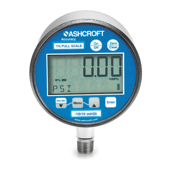
- Page 2 Optional 4-20mA output, switching and line- power add to the versatility of the gauge. With the range printed on the keypad, Ashcroft digital gauges meet ASME B40.7 specification. See a complete listing of product features and specifications on pages 16.
-
Page 3: Table Of Contents
TABLE OF CONTENTS Quick Reference ..........4-5 Keypad Functions ..........6-8 • ON/OFF KEY • ZERO/CLEAR KEY • MIN/MAX KEY (down arrow key) • MENU KEY • BACKLITE KEY (up arrow key) • ENTER KEY MENU Functions (MENU Mode) ........8-15 • Engineering Units •... - Page 4 QUICK RE .88˝ high digital display (4 ⁄ ˝ case) .60 high digital display(3˝ case) Bar graph % of full scale Flashing display when unit pressured below zero Press to indicate minimum or maximum pressure gauge has measured Press again to return to pressure units Press to read menu UPDATE RATE...
- Page 5 EFERENCE Press to turn unit on or off While in unit of measurement mode (eg: psi), press the ZERO CLEAR button to rezero the gauge. This feature functions when displayed pressure is within ±5% or 10% of zero value Flashing display when unit pressurized beyond full-scale This bar graph indicates battery level;...
-
Page 6: Keypad Functions
KEYPAD FUNCTIONS Turns the gauge on and off. When pressing the ON/OFF key while in the off position, gauge start- ON/OFF up display first indicates the software version followed by the model number and gauge pres- sure range. The gauge will then display indicated pressure and be ready for use. -
Page 7: (Down Arrow Key)
KEYPAD FUNCTIONS This key allows for customization of the gauge. Pressing the MENU key allows cycling through MENU the main MENU items; UNITS, CONFIG, GRAPH, OFF, UPDAT & DAMP. Any item changed in the Menu become the new default setting(s). Revised settings are saved in the event of power loss. - Page 8 KEYPAD FUNCTIONS This key allows for selecting gauge features in the menu finalizing selection. Use of the enter key is ENTER described throughout operating instructions. MENU OPTIONS UNITS: 12 units of measurement are available: psi, mmHG, O with three temperature options: 20°C, 60°F, 4°C*, mBar, inHg, ftH O, mPa, kPa, kg/cm and bar.
-
Page 9: Menu Functions (Menu Mode)
MENU FUNCTIONS How to Use Your Menu Functions To set a user password (SETPW): Step 1: Press the MENU key on the keypad Step 2: Press the (up arrow key) or (down arrow key) until the word CONFIG appears. Step 3: Press ENTER. The word SETPW appears on the gauge display Step 4: Press ENTER. - Page 10 MENU FUNCTIONS To use RECAL option: Step 1: Press the MENU key on the keypad Step 2: Press the (up arrow key) or (down arrow key) on the keypad until the word CONFIG appears. Step 3: Press ENTER. Step 4: Enter user password if it has been programmed. Step 5: Press (up arrow key) or (down arrow key)
- Page 11 MENU FUNCTIONS Note: Calibration of Zero, mid-scale or span can be set inde- pendently of each other. For instance, if only full-scale cali- bration is required, press the (down arrow key) until the gauge display indicates full-scale pressure. Press Enter and proceed as indicated above.
- Page 12 MENU FUNCTIONS Step 3: press ENTER. The current setting (ENAB or dISAB) will be displayed. Step 4: Press the (up arrow key) or (down arrow key) on the keypad to select a setting. Step 5: Press ENTER To finalize the setting. GRAPH: This option allows the user to change the BAR graph on the gauge display to correspond to any desired pressure within the pressure limits of the gauge.
- Page 13 MENU FUNCTIONS Step 5: Press the ENTER key to finalize your choice. The gauge display will now display SET. After two seconds the screen will display the pressure value for 0% on the top line. The middle line indicates the bar graph at 100% of fullscale.
- Page 14 MENU FUNCTIONS Step 2: Press the (up arrow key) or (down arrow key) until the word UPDATE appears. Step 3: Press ENTER. Step 4: Press the (up arrow key) or (down arrow key) to select an update rate. Step 5: Press ENTER to finalize the selection. DAMP or dampening: with five different options, this mode allows for taking process pressure readings and averaging them.
- Page 15 MENU FUNCTIONS position within the pressure range. The bottom line will display SETPT (blinking). SETPT is switch setpoint on rising pressure. Note: Setpoints are limited to the full-scale pressure range of the gauge. Step 4: Press the (up arrow key) or (down arrow key) on the keypad to increase or decrease switch set-point Step 5: Press the ENTER key to finalize switch setpoint.
-
Page 16: Engineering Units
DIGITAL INDUSTRIAL GAUGE SPECIFICATIONS Type: 2074 (battery), 2174 (loop), 2274 (line) Accuracy: .25% Full Scale, terminal point Case Size: 3˝, 4 ⁄ ˝ Case Material: 3˝ SS, 4 ⁄ ˝ fiberglass reinforced thermoplastic or black epoxy coated aluminum Case Encl. Rating:... -
Page 17: Display Messages
DIGITAL INDUSTRIAL GAUGE RANGES Note: Rows listed are not the equivalent of each other. in.Hg Comp. mmHg in.Hg Bar/ mBar (vacuum) (psi) (pressure) (pressure) –15/0/15 1000 –15/0/30 1000 1500 –15/0/60 2000 1000 2000 –15/0/100 3000 2500 5000 4000 10,000 5000 1000 6000 1000... -
Page 18: Wiring Diagrams
WIRING DIAGRAM Loop Powered 4-20mA (Type 2174) 2 conductor, 20 AWG shielded (+ exec.) A Black (– exec.) B Shield LOOP+ LOOP– ECND D10 C14 T9 F1D1 FID2 FID6 R22 R20 FID4 Sensor Input FID3 Battery Input 321CO21– DQ/TB 2003 +24V EGND Keypad Input... - Page 19 Load Limitations 4-20mA Output Only 1000 OPERATING REGION Loop Supply Voltage (Vdc) Vdc MIN = 12V + [0.022A X (RL) ] = Loop Resistance (ohms) = Sense Resistance (ohms) = Wiring Resistance (ohms) – 19 –...
-
Page 20: Wiring Diagrams
WIRING DIAGRAM Line Powered (Type 2274) 2 conductor, 20 AWG shielded F1D1 FID2 FID6 R22 R20 FID4 Sensor Input FID3 Battery Input 321CO21– DQ/TB 2003 +24V EGND Keypad Input Shield Black (–exec.) D Red (+exec.) C POWER SUPPL Y – Red (C) GAUGE ( –... - Page 21 WIRING DIAGRAM Line Powered with (1) SPDT switch (Type 2274 XU1) 5 conductor, 22 AWG shielded (–exec.) F (+exec.) E POWER SUPPL Y – (–) Black (F) GAUGE V– White (NO) • Brown (Common) Green (NC) Installation Procedure for 2274 XU1: ESD precautions should be taken.
- Page 22 WIRING DIAGRAM Line Powered with (2) SPDT switches (Type 2274 XU2) 8 conductor, 22 AWG shielded SWITCH 1 (N.O .) White (N. C. ) Green (COM) Brown ISO 1 F1D1 SWITCH 2 FID2 ISO 2 (N.C.) Yellow FID6 (N.O.) Blue R22 R20 FID4 (COM) Orange...
- Page 23 Installation Procedure for 2274 XU2: ESD precautions should be taken. See page 31 for details. 1. Ensure all power is off/disconnected from the circuit. 2. Connect the red wire (G) to the positive power terminal. 3. Connect the black wire (H) to the positive meter terminal. Wiring Switch 1: Normally Open: Use the white and brown wires.
- Page 24 WIRING DIAGRAM Line Powered/Loop Powered 4-20mA (Type 2274 XAO) 4 conductor, 20 AWG shielded Black (J) LOOP+ LOOP– ECND D10 C14 T9 F1D1 FID2 FID6 R22 R20 FID4 Sensor Input FID3 Battery Input 321CO21– DQ/TB 2003 +24V EGND Keypad Input Shield Green (L) White (K)
- Page 25 Installation Procedure for 2274 XAO: ESD precautions should be taken. See page 31 for details. 1. Ensure all power is off/disconnected from the circuit. 2. Connect the white wire (K) to the positive power terminal. 3. Connect the green wire (L) to the negative power terminal. 4.
- Page 26 WIRING DIAGRAM Line Powered/Loop Powered 4-20mA with (1) SPDT switch (Type 2274 XAOU1) 7 conductor, 22 AWG shielded Red M Blac k N (N.O.) Blue (N.C.) Orange (COM) Brown LOOP+ LOOP– ECND D10 C14 T9 ISO1 F1D1 FID2 ISO2 FID6 R22 R20 FID4 Sensor Input...
- Page 27 Installation Procedure for 2274 XAOU1: ESD precautions should be taken. See page 31 for details. 1. Ensure all power is off/disconnected from the circuit. 2. Connect the white wire (P) to the positive power terminal. 3. Connect the green wire (O) to the negative power terminal. 4.
- Page 28 WIRING DIAGRAM Line Powered/Loop Powered 4-20mA with (2) SPDT switches (Type 2274 XAOU2) 10 conductor, 22 AWG shielded Red Q Black R SWITCH 1 (N.O .) Blue (N.C .) Orang e (COM) Br ow n LOOP+ LOOP– ECND D10 C14 T9 ISO1 F1D1 FID2...
- Page 29 Installation Procedure for 2274 XAOU2: ESD precautions should be taken. See page 31 for details. 1. Ensure all power is off/disconnected from the circuit. 2. Connect the white wire (T) to the positive power terminal. 3. Connect the green wire (S) to the negative power terminal. 4.
- Page 30 BODY OF THE GAUGE. DOING SO MAY DAMAGE THE GAUGE AND MAKE THE GAUGE INOPERABLE. Battery Installation and Replacement: The 3˝ Type 2074 comes with two AA alkaline batteries installed. For battery replacement use; • Duracell AA alkaline, MN1500 LR06 1.5V The 4 ⁄...
- Page 31 ESD PRECAUTIONS Care should be taken to minimize exposure to ESD. Proper proto-call should be followed as outlined in: ANSI/ESD S20.20-2007 ESD ADV1.0-2009 ANSI/ESD S541-2008 Additional ESD Precautions on Proper Handling: Avoid carpets in cool, dry areas as well as other static generating materials such as plastic, cellophane, paper, or cardboard.
-
Page 32: Mounting
˝ CASE THICKNESS PANEL Willy Instrumentos de Medição e Controle Ltda. (An Ashcroft® Inc. Company) Rua João Pessoa, 620 - São Caetano do Sul - São Paulo - Brazil - 09520-000 Tel.: (55 11) 4224-7400 • Fax: (55 11) 4224-7477 vendas@ashcroft.com...
Need help?
Do you have a question about the 2074 and is the answer not in the manual?
Questions and answers