Table of Contents
Advertisement
Quick Links
Installation and Maintenance
Instruction Manual
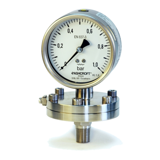
Diaphragm pressure gauge, model P5500 and P6500
for industrial application
In the following configuration:
• ###P5500/P6500### diaphragm pressure gauge without switching contact
• ###P5500/P6500### #### diaphragm pressure gauge with magnetic spring or inductive
proximity switches
IM-P5500-E-Rev 0
07/2011
Page 1 of 8
P/N 095I102-01EN
Advertisement
Table of Contents

Related Manuals for Ashcroft P6500


Summary of Contents for Ashcroft P6500
- Page 1 Diaphragm pressure gauge, model P5500 and P6500 for industrial application In the following configuration: • ###P5500/P6500### diaphragm pressure gauge without switching contact • ###P5500/P6500### #### diaphragm pressure gauge with magnetic spring or inductive proximity switches IM-P5500-E-Rev 0 07/2011 Page 1 of 8...
- Page 2 Fault table ................................8 Conduct following fault rectification ........................8 Removal, disposal ..............................8 10.1 Safety ................................8 10.2 Removal ................................8 10.3 Disposal ................................8 Appendix ................................. 8 11.1 Data sheet for diaphragm pressure gauge P5500/P6500 ................8 Page 2 of 8...
- Page 3 For the product described here, we offer a warranty pursuant to Section 6 Guarantee in Respect of Defects in our General Terms and Conditions of Delivery and Payment. 1.6 Manufacturer’s address, customer services Ashcroft Instruments GmbH Tel.: +49 (0) 2401/808-888 Fax.:...
- Page 4 2.3 Operator’s responsibility Safety instructions for proper operation of the device must be respected. They are to be provided by the operator for use by the respective personnel for installation, servicing, inspection and operation. Risks from electrical energy and from the released energy of the medium, from escaping media and from improper connection of the device must be eliminated.
- Page 5 The pressure gauge has a plug capable of blowing out on the rear wall of the housing (Model P5500) or a rear wall capable of blowing out (Model P6500). These act as a safety feature pursuant to EN 837-3 and simultaneously allow for temperature compensation for the housing, via a rubber membrane.
- Page 6 7 Assembly/Installation 7.1 Safety To ensure safe working during installation and servicing, suitable shut-off valves must be installed in the plant (see 5.4 Accessories), enabling the device: To be depressurized or taken out of operation; To be disconnected from the mains supply for repair or checks within the relevant plant; ...
- Page 7 7.4 Starting up The precondition for start-up is proper installation of all electrical feed lines and metering pipes. All connecting lines must be laid such that no mechanical forces can act on the device. Before start-up, the seal on the pressurized connection line must be checked. 7.4.1 Zero point adjustment The pressure gauges are supplied calibrated ex works, so that as a rule there is no need for calibration works at the installation point.
- Page 8 Please help to protect the environment and dispose of or recycle the devices and components used in accordance with the applicable regulations. 11 Appendix 11.1 Data sheet for diaphragm pressure gauge P5500/P6500 Detailed data sheet is available from suppliers website (see 1.6 Manufacturer’s address, customer services) This Table refers to specific documents:...
Need help?
Do you have a question about the P6500 and is the answer not in the manual?
Questions and answers