Advertisement
Quick Links
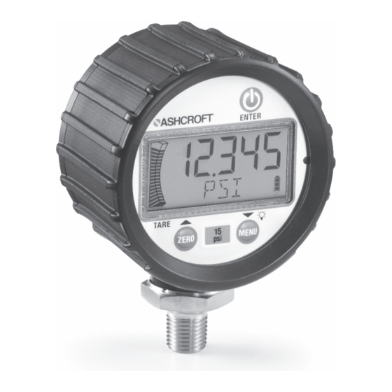
Installation and Operating
Instructions for General
Purpose Digital Pressure
Gauge Type DG25
Ashcroft Inc. 250 East Main Street, Stratford, CT 06614 USA
Tel: 203-378-8281, Fax: 203-385-0402 www.ashcroft.com
All sales subject to standard terms and conditions of sale.
© 2017 Ashcroft Inc. I&M006-10197 DG25 02/2017
1
Advertisement

Related Manuals for Ashcroft DG25


Summary of Contents for Ashcroft DG25
- Page 1 Instructions for General Purpose Digital Pressure Gauge Type DG25 Ashcroft Inc. 250 East Main Street, Stratford, CT 06614 USA Tel: 203-378-8281, Fax: 203-385-0402 www.ashcroft.com All sales subject to standard terms and conditions of sale. © 2017 Ashcroft Inc. I&M006-10197 DG25 02/2017...
-
Page 3: Installation
Symptoms of fluid hammer and surge’s dam- sure containing parts, or other misuse. aging effects: Consult Ashcroft Inc. Stratford, Connecticut, • Digital Gauge exhibits large zero offset. USA before installing if there are any ques- • Digital Gauge pressure display remains tions or concerns. -
Page 4: General Information
4. GENERAL INFORMATION: Keypad: © Power On-Off / Enter © Zero / Up Arrow / Tare Tare ZERO © Menu Selection / Down / Backlight Arrow M ENU Key presses are short less than 0.5 seconds or long greater than 0.5 seconds... -
Page 5: Lcd Display
LCD DISPLAY: LCD functions: 5 numerical digits for pressure display. 20 segment pressure range bar graph – each segment equals 5% of range. Sleep and Backlight Timer symbols. Maximum / Minimum Pressure and Tare icons. 5 character alpha-numeric digit display. 4 segment battery life indicator. - Page 6 Note: Key presses designated as short (less Zero Function: © than 0.5 sec) are indicated by “ ” ICON Press . Upon release, the numeric ZERO Key presses designated as long (greater than display momentarily disappears and “ZERO” 0.5 sec.) are indicated by “ ”...
- Page 7 Tare Function: Programming: Subtracts current pressure value from value To enter menu mode © displayed in Measurement mode. 1. Press and release to proceed M ENU In Measurement mode, apply desired pressure to programming mode. © © © press , to enable the tare function. The ZERO 2.
- Page 8 Custom Units of Measure Once the desired value is displayed, press © button to lock it in place. Now Allows a user to define a custom unit of meas- the next digit to the right will begin blinking. ure, user must enter the full scale value of the Repeat this procedure for all 5 digits.
- Page 9 Maximum / Minimum: Timer: Displays maximum / minimum pressure values; Controls how long the gauge will remain pow- © this is initiated upon powering the unit or since ered ON once the Power key is pressed. © © the values were cleared. 1.
- Page 10 Light: Update: Determines how long the back light will remain Utilized to select the rate at which the displayed ON after any key is pressed in Measurement or pressure value is updated on the screen. This Menu Modes (Note: The timer is reset with any function is used when rapid changes in pres- key being pressed.) sure cause “flutter”...
- Page 11 Z-Lock: Re-Calibration: Utilized to prevent inadvertent re-zeroing of the Provides the user the ability to field calibrate the instrument. product. Original factory calibration is perma- © © nently retained in memory and can be recalled at 1. In Menu mode, press until any time.
- Page 12 8. Display flashes “APPLY/ REF/ PSI/ THEN/ Graph: PRESS/ ENTER/ TO/ START/ OR/ OTHER/ Provides the user the ability to modify pressure TO/ ABORT”; apply the pressure indicated values dictating the minimum / maximum indi- in numeric display to gauge and press cations over the 20 segment bar graph.
- Page 13 6. To program minimum graph percentage, Reset: the display will indicate 0 0 with the right Returns the product to the factory default val- digit flashing, the bottom most segment ues.Preserves field calibration. Factory calibra- of the bar graph will flash, and the dis- tion can be restored in the “RECAL”...
- Page 14 Changing Batteries: Grip knurled back cover and rotate counter- clockwise until the ‘unlock’ icon is in alignment with the arrow – this is on the housing at the base of the pressure connection. WARNING: Misuse may cause injury or damage. Refer to ASME B40.100 Remove cover by pulling straight back and replace AA alkaline batteries accordingly;...
- Page 15 Pressure Range: Dimensions: Proof Pressure: Vac-2000psi 200% % of Span 3000-5000psi: 150% 69.36mm Ø2.73in 7500-25,000psi: 120% Burst Pressure: Vac-2000psi: 800% % of Span 3000-5000psi: 500% 7500-25,000psi: 300% Environmental Specifications: 50.5mm 1.99in Temperature 67mm 2.64in Storage: Batteries removed: –20°C to 80°C (–4°F to 176°F) 1/4 NPT Male Batteries installed: –20°C to 60°C (–4°F to 140°F)
- Page 16 Ashcroft Inc. 250 East Main Street, Stratford, CT 06614 USA Tel: 203-378-8281, Fax: 203-385-0402, www.ashcroft.com All sales subject to standard terms and conditions of sale. © 2017 Ashcroft Inc. I&M006-10197 DG25 02/2017...
Need help?
Do you have a question about the DG25 and is the answer not in the manual?
Questions and answers