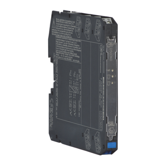
Summarization of Contents
Characteristics
General Description
Details the unit's suitability for SIL 2 systems, configuration options, fault detection, and mounting.
Functional Safety Management Certification
States G.M. International's certification by TUV for IEC61508.
Technical Data
Electrical Specifications
Covers supply, current, power, isolation, input/output levels, and contact ratings.
Mechanical & Performance
Details operational life, switching times, bounce time, and frequency response.
Compatibility & Approvals
Lists compliance standards, safety certifications, and product approvals.
Environmental & Installation
Covers operating conditions, mounting, location, protection class, dimensions, and connections.
Ordering Information
Model and Accessories
Describes available models and related accessories for ordering.
Front Panel and Features
Key Features and Safety Ratings
Covers SIL rating, PFDavg, SFF, systematic capability, input/output modes, fault detection, isolation, EMC, programmability.
Certifications and Installation Notes
Lists certifications and installation advantages like simplified installation.
Terminal Block Connections
Hazardous Area Connections
Details terminal assignments for the hazardous area side.
Safe Area Connections
Details terminal assignments for the safe area side.
Parameters Table
Intrinsically Safe Parameters
Details Uo/Voc, Io/Isc, Po/Po for D5036 and corresponding device limits.
Capacitance and Inductance Parameters
Lists Co/Ca, Lo/La, Lo/Ro for D5036 and device+cable limits.
Cable Parameter Guidelines
Provides default cable capacitance and inductance values.
Function Diagram
D5036D Functionality
Illustrates input/output connections and operations for the D5036D model.
D5036S Functionality
Illustrates input/output connections and operations for the D5036S model.
Fault Detection Wiring
Explains the use of resistors for line fault detection.
Application for D5036D
Operating Modes
Describes OFF and ON operation states for the D5036D module.
Input/Output State Mapping
Details how input signals map to output states and LEDs.
Safety Function and Failure Behavior
Explains failure modes, HFT, and failure rates for D5036D.
PFDavg and Proof Test Tables
Presents PFDavg data based on proof test intervals.
Application for D5036S
Operating Modes
Describes OFF and ON operation states for the D5036S module.
Input/Output State Mapping
Details how input signals map to output states and LEDs.
Safety Function and Failure Behavior
Explains failure modes, HFT, and failure rates for D5036S.
PFDavg and Proof Test Tables
Presents PFDavg data based on proof test intervals.
Testing Procedure at T-proof
Proof Test Steps
Outlines the sequential steps for performing a proof test.
Warnings for Testing
Provides critical warnings regarding testing procedures and equipment.
Operation
Module Configuration and Fault Detection
Explains module configuration for switches/proximity detectors and fault detection.
Installation and Wiring
Covers DIN-Rail mounting, electrical connections, and intrinsic safety wiring.
Start-up Verification
Details checks and steps for verifying correct operation after installation.
Configuration
D5036D DIP Switch Settings
Illustrates DIP switch settings for CH1 and CH2 on the D5036D model.
D5036D Configuration Summary
Summarizes DIP switch configurations for line fault detection and I/O operation.
Configuration
D5036S DIP Switch Settings
Illustrates DIP switch settings for CH1 on the D5036S model.
D5036S Configuration Summary
Summarizes DIP switch configurations for line fault detection and I/O operation.
D5036D Configuration Summary Table
Provides a summary table for D5036D DIP switch configurations.
D5036S Configuration Summary Table
Provides a summary table for D5036S DIP switch configurations.


Need help?
Do you have a question about the D5036D and is the answer not in the manual?
Questions and answers