
Related Manuals for GMI D5039S Series


Summary of Contents for GMI D5039S Series
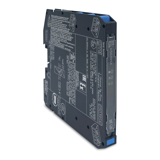
- Page 1 D5039S*, D5039D*, D5039X* INSTRUCTION MANUAL I.S. SIL2 Line-Fault Transp. Switch/Prox. Repeater, DIN-Rail and Termination Board Models D5039S*, D5039D*, D5039X* D5039 - I.S. SIL2 Line-Fault Transp. Switch/Prox. Repeater G.M. International ISM0428-1...
-
Page 2: Technical Data
Characteristics General Description: The Switch/Proximity Detector Repeater D5039 is a module suitable for applications requiring SIL 2 level in safety related systems for high risk industries. The unit can be configured for switches or proximity detectors, located in Hazardous Area, and repeats the input state to the output in Safe Area. The output port can assume two different impedance values (RL or RH) or it can open completely. -
Page 3: Terminal Block Connections
Front Panel and Features SIL 2 (low demand mode of operation) according to IEC 61508:2010 Ed.2 with Tproof = 6 / 12 yrs (≤ 10 / >10 % of total SIF). SC 3: Systematic Capability SIL 3 Input from Zone 0/Div. - Page 4 Parameters Table In the system safety analysis, always check the Hazardous Area/Hazardous Locations devices to conform with the related system documentation, if the device is Intrinsically Safe check its suitability for the Hazardous Area/Hazardous Locations and group encountered and that its maximum allowable voltage, current, power (Ui/Vmax, Ii/Imax, Pi/Pi) are not exceeded by the safety parameters (Uo/Voc, Io/Isc, Po/Po) of the D5039 series Associated Apparatus connected to it.
-
Page 5: Function Diagram
Function Diagram HAZARDOUS AREA ZONE 0 (ZONE 20) GROUP IIC, SAFE AREA, ZONE 2 GROUP IIC T4, HAZARDOUS LOCATIONS CLASS I, DIVISION 1, GROUPS A, B, C, D, NON HAZARDOUS LOCATIONS, CLASS I, DIVISION 2, CLASS II, DIVISION 1, GROUPS E, F, G, CLASS III, DIVISION 1, GROUPS A, B, C, D T-Code T4, CLASS I, ZONE 2, GROUP IIC T4 CLASS I, ZONE 0, GROUP IIC MODEL D5039S... -
Page 6: Operation
Warning D5039 series is isolated Intrinsically Safe Associated Apparatus installed into standard EN/IEC60715 TH 35 DIN‑Rail located in Safe Area or Zone 2, Group IIC, Temperature T4 or Class I, Division 2, Group A, B, C, D, T4 Hazardous Area within the specified operating temperature limits Tamb ‑40 to +70 °C, and connected to equipment with a maximum limit for power supply Um of 250 Vrms or Vdc. - Page 7 Configuration A configuration DIP switch is located on component side of PCB. This switch allows the configuration of input/output relationship, fault detection functions and operating mode. Configuration of channel 2 is relevant only for D5039D*. Dip switch factory settings. Switches 1 and 3 are ON, switches 2 and 4 are OFF ON OFF ON OFF Enabled Line fault...
Need help?
Do you have a question about the D5039S Series and is the answer not in the manual?
Questions and answers