Table of Contents
Advertisement
Quick Links
Advertisement
Table of Contents

Related Manuals for Asus PIKE 2008 IMR


Summary of Contents for Asus PIKE 2008 IMR
- Page 1 PIKE 2008/IMR LSISAS RAID card User Guide...
- Page 2 Product warranty or service will not be extended if: (1) the product is repaired, modified or altered, unless such repair, modification of alteration is authorized in writing by ASUS; or (2) the serial number of the product is defaced or missing.
-
Page 3: Table Of Contents
Contents Contents ...................... iii About this guide ..................iv PIKE 2008/IMR specifications summary ........... vi Chapter 1: Product introduction Welcome! ..................1-2 Package contents ................. 1-2 Card layout ................... 1-3 System requirements ..............1-3 Card installation ................1-4 Chapter 2: RAID configuration Setting up RAID ................ -
Page 4: About This Guide
Refer to the following sources for additional information and for product and software updates. ASUS websites The ASUS website provides updated information on ASUS hardware and software products. Refer to the ASUS contact information. Optional documentation Your product package may include optional documentation, such as warranty flyers, that may have been added by your dealer. -
Page 5: Conventions Used In This Guide
Conventions used in this guide To make sure that you perform certain tasks properly, take note of the following symbols used throughout this manual. DANGER/WARNING: Information to prevent injury to yourself when trying to complete a task. CAUTION: Information to prevent damage to the components when trying to complete a task. -
Page 6: Pike 2008/Imr Specifications Summary
PIKE 2008/IMR specifications summary Controller LSISAS2008 Interface ASUS PIKE interface Ports 8 ports Support device SAS/SAS II devices SATA/SATA II/SATA III devices Data transfer rate SATA III and SAS II 6Gb/s per PHY RAID level RAID 0/RAID 1/RAID 10/RAID 5/RAID 50... -
Page 7: Chapter 1: Product Introduction
This chapter offers the PIKE 2008/IMR SAS RAID card features and the new technologies it supports. Chapter 1: Product introduction... -
Page 8: Welcome
PIKE 2008/IMR SAS RAID card! ® The ASUS PIKE 2008/IMR allows you to create RAID 0, RAID 1, RAID 10, RAID 5, and RAID 50 sets from SATA/SATA II/SATA III/SAS/SAS II hard disk drives connected to the SAS connectors on the motherboard. -
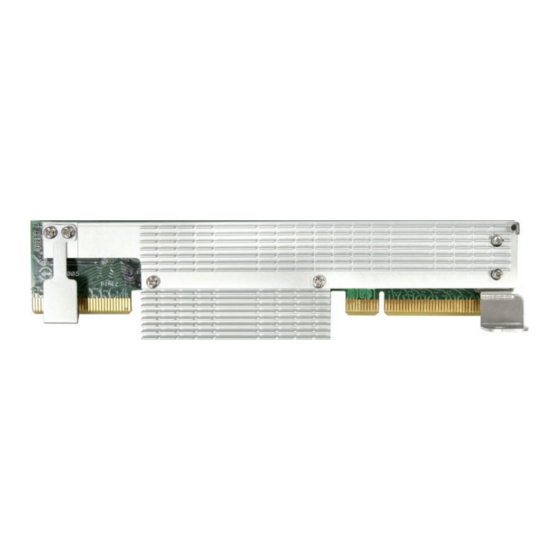
Page 9: Card Layout
The illustration below shows the major components of the RAID card. ASUS PIKE interface-1: PCI-E x8 ASUS PIKE interface-2: 8-port SAS signal with SGPIO interface* SAS RAID card status LED (lights up and blinks to indicate that the card is... -
Page 10: Card Installation
Follow the below instructions to install the RAID card on your motherboard. For 2U, 5U, or pedestal server To install ASUS PIKE 2008/IMR SAS RAID card on a 2U, 5U, or pedestal server Locate the PIKE RAID card slot on the motherboard. - Page 11 Connect the hard disk drives to the SAS connectors on the motherboard. To uninstall ASUS PIKE 2008/IMR SAS RAID card from a 2U, 5U, or pedestal server Disconnect all SAS hard disk drives from the motherboard. Remove the screw that secures the RAID card to the motherboard.
- Page 12 For 1U server You have to remove the outer heatsink of ASUS PIKE 2008/IMR SAS RAID card to install the card in a 1U server. To install ASUS PIKE 2008/IMR SAS RAID card on a 1U server Remove the two screws that secure the heatsink bracket on the back of the SAS RAID card.
- Page 13 RAID card with the PIKE RAID card slot. Insert the RAID card into the PIKE RAID card slot. Ensure the card is completely inserted into the card slot. Connect the hard disk drives to the SAS connectors on the motherboard. ASUS PIKE 2008/IMR...
- Page 14 Chapter 1: Product introduction...
-
Page 15: Chapter 2: Raid Configuration
This chapter provides instructions on setting up, creating, and configuring RAID sets using the available utilities. Chapter 2: RAID configuration... -
Page 16: Setting Up Raid
Setting up RAID The RAID card supports RAID 0, RAID 1, RAID 10, RAID 5, and RAID 50. 2.1.1 RAID definitions RAID 0 (Data striping) optimizes two identical hard disk drives to read and write data in parallel, interleaved stacks. Two hard disks perform the same work as a single drive but at a sustained data transfer rate, double that of a single disk alone, thus improving data access and storage. -
Page 17: Installing Hard Disk Drives
Connect a SAS signal cable to the signal connector at the back of each drive and to the SAS connector on the motherboard. Connect a power cable to the power connector on each drive. ASUS PIKE 2008/IMR... -
Page 18: Lsi Webbios Configuration Utility
LSI WebBIOS Configuration Utility The LSI WebBIOS Configuration Utility (CU) is an integrated RAID solution that allows you to create RAID 0, 1, 10, 5, and 50 sets from SATA/SATA II/SATA III/SAS/ SAS II hard disk drives supported by the LSI SAS 2008 controller. You can also use the WebBIOS CU to do the following tasks: •... -
Page 19: Starting The Webbios Cu
0 Virtual Drive(s) handled by BIOS Press <Ctrl><H> for WebBIOS or press <Ctrl><Y> for Preboot CLI The Adapter Selection screen appears. If the system has multiple SAS adapters, select an adapter. Click Start to continue. The main WebBIOS CU screen appears. ASUS PIKE 2008/IMR... -
Page 20: Webbios Cu Main Screen Options
2.2.2 WebBIOS CU main screen options This is the Physical View screen which displays the drives that are connected to the controller. To toggle between the physical view and logical view of the storage devices connected to the controller, click Physical View or Logical View in the menu on the left. - Page 21 Physical View/Logical View: Select this to toggle between the Physical View • and Logical View screens. Events: Select this to view system events in the Event Information screen. • Exit: Select this to exit the WebBIOS CU and continue with system boot. • ASUS PIKE 2008/IMR...
-
Page 22: Creating A Storage Configuration
2.2.3 Creating a Storage Configuration This section explains how to use the WebBIOS CU Configuration Wizard to configure RAID arrays and virtual drives. Selecting the Configuration with the Configuration Wizard Follow these steps to start the Configuration Wizard, and select a configuration option and mode: Click Configuration Wizard on the WebBIOS main screen. -
Page 23: Using Automatic Configuration
Click Add To Array to move the drives to a proposed drive group configuration in the Drive Groups panel on the right, as shown in the right figure. If you need to undo the changes, click the Reclaim button. ASUS PIKE 2008/IMR... - Page 24 When you have finished selecting drives for the drive group, click Accept DG. Click Next. The Span Definition screen appears. Select one of the available drive groups, and then click Add to SPAN. When finish, click Next. The Virtual Drive Definition screen appears, as shown in the right figure.
- Page 25 Otherwise, click Back to return to the previous screens and change the configuration. 12. If you accept the configuration, click Yes at the prompt to save the configuration. 13. Click Yes at the prompt to start initialization. ASUS PIKE 2008/IMR 2-11...
- Page 26 Using Manual Configuration: RAID 1 In RAID 1, the RAID controller duplicates all data from one drive to a second drive. RAID 1 provides complete data redundancy, but at the cost of doubling the required data storage capacity. It is appropriate for small databases or any other environment that requires fault tolerance but small capacity.
- Page 27 Otherwise, click Back to return to the previous screens and change the configuration. 12. If you accept the configuration, click Yes at the prompt to save the configuration. 13. Click Yes at the prompt to start initialization. ASUS PIKE 2008/IMR 2-13...
- Page 28 Using Manual Configuration: RAID 5 RAID 5 uses drive striping at the block level and parity. In RAID 5, the parity information is written to all drives. It is best suited for networks that perform a lot of small input/output (I/O) transactions simultaneously. RAID 5 provides data redundancy, high read rates, and good performance in most environments.
- Page 29 Otherwise, click Back to return to the previous screens and change the configuration. 12. If you accept the configuration, click Yes at the prompt to save the configuration. 13. Click Yes at the prompt to start initialization. ASUS PIKE 2008/IMR 2-15...
- Page 30 Using Manual Configuration: RAID 10 RAID 10, a combination of RAID 1 and RAID 0, has mirrored drives. It breaks up data into smaller blocks, then stripes the blocks of data to each RAID 1 drive group. Each RAID 1 drive group then duplicates its data to its other drive. The size of each block is determined by the strip size parameter.
- Page 31 Write Policy: Specify the write policy for this virtual drive: • ◊ Write Through: In Writethrough mode the controller sends a data transfer completion signal to the host when the disk subsystem has received all the data in a transaction. This is the default. ASUS PIKE 2008/IMR 2-17...
- Page 32 IO Policy: The IO Policy applies to reads on a specific virtual drive. It • does not affect the read ahead cache. ◊ Direct: In Direct I/O mode, reads are not buffered in cache memory. Data is transferred to the cache and the host concurrently. If the same data block is read again, it comes from cache memory.
- Page 33 Both drive groups display in the right frame under Span. 11. When finish, click Next. The Virtual Drive Definition screen appears. You use this screen to select the RAID level, strip size, read policy, and other attributes for the new virtual drive(s). ASUS PIKE 2008/IMR 2-19...
- Page 34 12. Hold <Ctrl> while selecting two drive groups with three or more drives each in the Configuration panel on the right. 13. Change the virtual drive options from the defaults listed on the screen as needed. Here are brief explanations of the virtual drive options: RAID Level: The drop-down menu lists the possible RAID levels for the •...
- Page 35 WebBIOS main menu, or click Back to return to the previous screens and change the configuration. 19. If you accept the configuration, click Yes at the prompt to save the configuration. 20. Click Yes at the prompt to start initialization. ASUS PIKE 2008/IMR 2-21...
-
Page 36: Viewing And Changing Device Properties
2.2.4 Viewing and Changing Device Properties This section explains how you can use the WebBIOS CU to view and change the properties for controllers, virtual drives, and drives. WebBIOS allows you to view information for the LSI SAS controller. To view the properties for the controller, click Controller Properties on the main WebBIOS screen. - Page 37 The following table describes the entries/options listed on the second and third Controller Properties screen. We recommend that you leave these options at their default settings to achieve the best performance, unless you have a specific reason for changing them. ASUS PIKE 2008/IMR 2-23...
- Page 38 Controller Properties Menu Options Option Description Set Factory Use this option to load the default MegaRAID WebBIOS CU settings. ® Defaults The default is [No]. Use this option to enable or disable Cluster mode. The default is [Disabled]. A cluster is a grouping of independent servers that can Cluster Mode access the same data storage and provide services to a common set of clients.
- Page 39 The default is [Disabled]. If you make changes to the options on this screen, click Submit to register them. If you change your mind, click Reset to return the options to their default values. ASUS PIKE 2008/IMR 2-25...
-
Page 40: Viewing And Changing Virtual Drive Properties
Viewing and Changing Virtual Drive Properties Access the Virtual Drive screen by clicking a virtual drive icon in the right panel on the WebBIOS CU main screen. The following figure shows the Virtual Drive screen. The Properties panel of this screen displays the virtual drive’s RAID level, state, capacity, and strip size. -
Page 41: Viewing Drive Properties
If you force offline a good drive that is part of a redundant drive group with a hot spare, the drive will rebuild to the hot spare drive. The drive you forced offline will go into the Unconfigured Bad state. Access the BIOS utility to set the drive to the Unconfigured Good state. ASUS PIKE 2008/IMR 2-27... - Page 42 Select Locate to make the LED flash on the drive. This works only if the drive • is installed in a drive enclosure. Select Stop Locate to disable the LED flash on the drive. • If the drive state is Unconfigured Good, four additional operations appear on this screen: Select Make Global HSP to make a global hot spare, available to all of the •...
-
Page 43: Viewing System Event Information
If you want, select different event criteria in the left panel, and click Go again to view a different sequence of events. Each event entry includes a timestamp and a description to help you determine when the event occurred and what it was. ASUS PIKE 2008/IMR 2-29... -
Page 44: Managing Configurations
2.2.6 Managing Configurations This section includes information about maintaining and managing storage configurations. Running a Consistency Check You should periodically run a consistency check on fault-tolerant virtual drives. A consistency check verifies that the redundancy data is correct and available for RAID 1, RAID 5, and RAID 10 arrays. -
Page 45: Importing Or Clearing A Foreign Configuration
Follow these steps to import or clear a foreign configuration: Click the drop-down list to show the configurations. The GUID (Global Unique Identifier) entries on the drop-down list are OEM names and will vary from one installation to another. ASUS PIKE 2008/IMR 2-31... - Page 46 Select a configuration or All Configurations. Perform one of the following steps: Click Preview to preview the • foreign configurations. The Foreign Configuration Preview screen appears, as shown in the right figure. Click Clear to clear the foreign • configurations and reuse the drives for another virtual drive.
- Page 47 Scenario #4: If the drives in a non-redundant virtual drive are removed, the controller considers the drives to have foreign configurations. Import or clear the foreign configuration. No rebuilds will occur after the import operation because there is no redundant data to rebuild the drives with. ASUS PIKE 2008/IMR 2-33...
-
Page 48: Megaraid Storage Manager
MegaRAID Storage Manager MegaRAID Storage Manager software enables you to configure, monitor, and maintain storage configurations on LSI SAS controllers. The MegaRAID Storage Manager graphical user interface (GUI) makes it easy for you to create and manage storage configurations. 2.3.1 Hardware and Software Requirements The hardware requirements for MegaRAID Storage Manager software are as follows:... - Page 49 Click Next to continue. On the next screen, accept the default Destination Folder, or click Change to select a different destination folder. Click Next to continue. The Setup Type screen appears, as shown in the following figure. ASUS PIKE 2008/IMR 2-35...
- Page 50 Select one of the Setup options. The options are fully explained in the screen text. Normally, you would select Complete if you are installing MegaRAID – Storage Manager software on a server. Select Custom Installation if you want to select individual program –...
- Page 51 (that is, servers with a complete installation of MegaRAID Storage Manager software), the server screen will appear, as shown in the following figure. The server screen will not list any servers. You can use this screen to manage systems remotely. ASUS PIKE 2008/IMR 2-37...
-
Page 52: Installing Megaraid Storage Manager Software For Linux
2.3.3 Installing MegaRAID Storage Manager Software for Linux Follow these steps if you need to install MegaRAID Storage Manager software on a system running Red Hat Linux or SUSE Linux: Copy the MSM_linux_installer...tar.gz file to a temporary folder. Untar the MSM_linux_installer...tar.gz file using the following command: tar -zxvf MSM_linux_installer...tar.gz A new disk directory is created. -
Page 53: Linux Error Messages
Exiting installation. This is the message that appears when the installation is complete. • RPM installation failed. This message indicates that the installation failed for some reason. Additional message text explains the cause of the failure. ASUS PIKE 2008/IMR 2-39... -
Page 54: Starting Megaraid Storage Manager Software
2.3.5 Starting MegaRAID Storage Manager Software Follow these steps to start MegaRAID Storage Manager software and view the main window: Start the program using the method required for your operating system environment: – To start MegaRAID Storage Manager software on a Microsoft Windows system, select Start >... - Page 55 You must enter the root/administrator user name and password to use Full Access mode. If your user name and password are correct for the Login mode you have chosen, the main MegaRAID Storage Manager window appears. ASUS PIKE 2008/IMR 2-41...
-
Page 56: Megaraid Storage Manager Window
2.3.6 MegaRAID Storage Manager Window After you log in, the dashboard view provides an overview of the system and covers the properties of the virtual drives and the physical drives, total capacity, configured capacity, unconfigured capacity, background operations in progress, MegaRAID Storage Manager features and their status (enabled or disabled), and actions you can perform, such as creating a virtual drive and updating the firmware, as shown in the following figure. - Page 57 A yellow circle to the right of an icon indicates that a device is running in a degraded state. For example, this icon indicates that a virtual drive is running in a degraded state because a drive has failed: ASUS PIKE 2008/IMR 2-43...
-
Page 58: Event Log Panel
Properties View Panel The right panel of the MegaRAID Storage Manager window has the Properties tab that displays information about the selected device. For example, if a controller icon is selected in the left panel, the Properties tab lists information such as the controller name, NVRAM size, and device port count. - Page 59 If this warning appears, click on the active content warning bar and enable the active content. • If you are using the Linux operating system, you must install Firefox ® Mozilla for the MegaRAID Storage Manager online help to display. ® ASUS PIKE 2008/IMR 2-45...
- Page 60 2-46 Chapter 2: RAID configuration...
-
Page 61: Chapter 3: Driver Installation
This chapter provides instructions for installing the RAID drivers on different operating systems. Chapter 3: Driver installation... -
Page 62: Raid Driver Installation
RAID driver installation After creating the RAID sets for your server system, you are now ready to install an operating system to the independent hard disk drive or bootable array. This part provides instructions on how to install or update the RAID card drivers. The RAID card driver might be included in the Linux OS installation CD, and could be loaded automatically during OS installation. - Page 63 RHEL 5 UP3 32/64 bit RHEL 5 UP4 32/64 bit RHEL 5 UP5 32/64 bit SLES 9 SP3 32 bit Place a blank, high-density floppy disk to the floppy disk drive. Press <Enter>. Follow screen instructions to create the driver disk. ASUS PIKE 2008/IMR...
-
Page 64: Windows ® Server 2003 Os
3.1.2 Windows Server 2003 OS ® During Windows Server 2003 OS installation ® To install the RAID card driver when installing Windows Server 2003 OS: ® Boot the computer using the Windows Server 2003 OS installation CD. The ® Window Setup starts. - Page 65 ENTER=Select F3=Exit The Windows Setup loads the RAID card drivers from the RAID driver disk. ® When next screen appears, press <Enter> to continue installation. Setup then proceeds with the OS installation. Follow screen instructions to continue. ASUS PIKE 2008/IMR...
- Page 66 After Windows Server 2003 OS installation ® To update the RAID card driver after installing Windows Server 2003 OS: ® Right-click the My Computer icon on the desktop and select Properties from the menu. Click the Hardware tab on the top, then click the Device Manager button. Double-click the LSI MRSASRoMB-8i item.
- Page 67 Toggle Don’t search. I will choose the driver to install, then click Next to continue. Insert the RAID driver disk you created earlier to the floppy disk drive. Highlight LSI Adapter, SAS2 2008 Falcon -StorPort, then click Have Disk. LSI Adapter, SAS2 2008 Falcon -StorPort ASUS PIKE 2008/IMR...
- Page 68 Select from the drop-down menu and locate the driver. 10. Click Next to start updating the driver. LSI Adapter, SAS2 2008 Falcon -StorPort 11. After completing driver update, click Finish to close the wizard. LSI Adapter, SAS2 2008 Falcon -StorPort Chapter 3: Driver installation...
-
Page 69: Red Hat ® Enterprise Linux Os 5
Enterprise RAID driver disk to the USB floppy disk drive, ® select OK, then press <Enter>. Insert Driver Disk Insert your driver disk into /dev/sda and press “OK” to continue. Back The drivers for the RAID card are installed to the system. ASUS PIKE 2008/IMR... - Page 70 When asked if you will load additional RAID controller drivers, select No, then press <Enter>. More Driver Disks? Do you wish to load any more driver disks? Select Skip and press <Enter> to continue. CD Found To begin testing the CD media before installation press OK.
-
Page 71: Suse Linux Os 11
When below screen appears, select the USB floppy disk drive (sdx) as the driver update medium. Select OK, then press <Enter>. Please choose the Driver Update medium. sda: USB Floppy sr0: CD-ROM, ASUS DRW-2014S1T Other device Back The drivers for the RAID controller are installed to the system. - Page 72 3-12 Chapter 3: Driver installation...
Need help?
Do you have a question about the PIKE 2008 IMR and is the answer not in the manual?
Questions and answers