Table of Contents
Advertisement
Quick Links
Service Overview
GA35DX_Service_manual
COPYRIGHT INFORMATION
No part of this manual, including the products and software described in it, may be reproduced,
transmitted, transcribed, stored in a retrieval system, or translated into any language in any form or by any means,
except documentation kept by the purchaser for backup purposes, without the express written permission of
ASUSTeK COMPUTER INC.("ASUS").
ASUS PROVIDES THIS MANUAL "AS IS"WITHOUT WARRANTY OF ANY KIND, EITHER EXPRESS
OR IMPLIED, INCLUDING BUT NOT LIMITED TO THE IMPLIED WARRANTIES OR CONDITIONS
OF MERCHANTABILITY OR FITNESS FOR A PARTICULAR PURPOSE. IN NO EVENT SHALL ASUS,
ITS DIRECTORS, OFFICERS, EMPLOYEES OR AGENTS BE LIABLE FOR ANY INDIRECT, SPECIAL,
INCIDENTAL, OR CONSEQUENTIAL DAMAGES (INCLUDING DAMAGES FOR LOSS OF PROFITS,
LOSS OF BUSINESS, LOSS OF USE OR DATA, INTERRUPTION OF BUSINESS AND THE LIKE),
EVEN IF ASUS HAS BEEN ADVISED OF THE POSSIBILITY OF SUCH DAMAGES ARISING FROM
ANY DEFECT OR ERROR INTHIS MANUAL OR PRODUCT.
Products and corporate names appearing in this manual may or may not be registered trademarks or copyrights of
their respective companies, and are used only for identification or explanation and to the owners' benefit, without
intent to infringe.
SPECIFICATIONS AND INFORMATION CONTAINED IN THIS MANUAL ARE FURNISHED FOR
INFORMATIONAL USE ONLY, AND ARE SUBJECTTO CHANGE AT ANY TIME WITHOUT
NOTICE, AND SHOULD NOT BE CONSTRUED AS A COMMITMENT BY ASUS. ASUS ASSUMES NO
RESPONSIBILITY OR LIABILITY FOR ANY ERRORS OR INACCURACIES THAT MAY APPEAR IN
THIS MANUAL, INCLUDING THE PRODUCTS AND SOFTWARE DESCRIBED IN IT.
Copyright ○
2023 ASUSTeK COMPUTER INC. All Rights Reserved.
c
LIMITATION OF LIABILITY
Circumstances may arise where because of a default on ASUS' part or other liability, you are entitled to recover
damages from ASUS. In each such instance, regardless of the basis on which you are entitled to claim damages
from ASUS, ASUS is liable for no more than damages for bodily injury (including death) and damage to real
property and tangible personal property; or any other actual and direct damages resulted from omission or failure
of performing legal duties under this Warranty Statement, up to the listed contract price of each product.
ASUS will only be responsible for or indemnify you for loss, damages or claims based in contract, tort or
infringement under this Warranty Statement.
1-1
V2.1
Advertisement
Table of Contents

Related Manuals for Asus GA35DX


Summary of Contents for Asus GA35DX
- Page 1 LIMITATION OF LIABILITY Circumstances may arise where because of a default on ASUS' part or other liability, you are entitled to recover damages from ASUS. In each such instance, regardless of the basis on which you are entitled to claim damages from ASUS, ASUS is liable for no more than damages for bodily injury (including death) and damage to real property and tangible personal property;...
- Page 2 Service Overview This limit also applies to ASUS' suppliers and its reseller. It is the maximum for which ASUS, its suppliers, and your reseller are collectively responsible. UNDER NO CIRCUMSTANCES IS ASUS LIABLE FOR ANY OF THE FOLLOWING: (1) THIRD-PARTY CLAIMS AGAINSTYOU FOR DAMAGES;...
-
Page 3: Service Overview
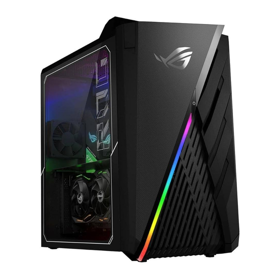
Desktop and necessary cautions and tools before performing any service and repairs. o provide the best service and support for the ASUS DESKTOP GA35DX series we have provided the below information for technicians from distributors and resellers to perform the complete Desktop disassembly and assembly. But before performing the procedures, please be sure to read through the overview in this chapter for component overview, cautions and tools to avoid any unwarranted damages to the Desktop’s hardware. - Page 4 Disassembly Procedure DESKTOP PC GA35DX Series Overview The illustrations below show the Desktop PC’s overview from front view, side view and back view. Most of the parts will be discussed in this manual. ● FRONT & TOP VIEW Refer to the following diagram to identify the components on this front of the system.
- Page 5 Disassembly Procedure 1.Power button. 2.USB 3.1 gen1 ports. 3.USB 3.1 gen1 Type-C ports. 4.Microphone port. 5. Headphone port. 6.Headset hanger. V2.7 2 - 5...
- Page 6 Disassembly Procedure V2.7 2 - 6...
- Page 7 Disassembly Procedure 1. DisplayPort. 2.HDMI port. 3.BIOS FLBK button. 4.BIOS FLBK port. 5.USB 3.2 gen2 ports. 6.USB 3.2 gen2 Type-C port. 7.Optical S/PDIF Out port. 8.Rear Speaker Out port (black). 9.Center/Subwoofer port (orange). 10.Microphone port (pink). 11.Line Out port (lime). V2.7 2 - 7...
- Page 8 Disassembly Procedure 12.Line In port (light blue). 13.Power connector. 14.Power switch. 15.Expansion slot brackets. 16.ASUS Graphics Cards (on selected models only). 17.LAN (RJ-45) port. 18.Air vents. 19.USB 3.1 gen2 ports. -------------------------------------------------------------------------------------------------------- V2.7 2 - 8...
- Page 9 Disassembly Procedure 1. DisplayPort. 2.HDMI port. 3.BIOS FLBK button. 4.BIOS FLBK port. 5.USB 3.2 gen2 ports. 6.USB 3.2 gen2 Type-C port. 7.Optical S/PDIF Out port. 8.Rear Speaker Out port (black). 9.Center/Subwoofer port (orange). 10.Microphone port (pink). 11.Line Out port (lime). 12.Line In port (light blue).
- Page 10 Disassembly Procedure 13.Power connector. 14.Power switch. 15.ASUS Graphics Cards (on selected models only). 16.LAN (RJ-45) port. 17.Air vents. 18.USB 3.1 gen2 ports. V2.7 2 - 10...
- Page 11 Disassembly Procedure Components The illustrations below show the components of the GA35DX. The following chapter includes all part numbers mentioned in service guide are used for reference only, actual part name depends on different SKU, if you need the exact part number for ordering please refer the Orderbook.
- Page 12 Disassembly Procedure CPU COOLER CPU LIQUID COOLER V2.7 2 - 12...
- Page 13 Disassembly Procedure THERMAL FAN GA35DX PCH SINK THERMAL FAN 12025COOLER AM4 V2.7 2 - 13...
- Page 14 Disassembly Procedure WLAN CARD MOTHER BOARD GA35DX MOS SINK GA35DX NB M2 SINK GA35DX M2 SINK V2.7 2 - 14...
-
Page 15: Led Board
Disassembly Procedure ROG STRIX X570-E PCH 1 ASSY M2 WIFI ADAPTER BOARD LED BOARD SIDE LED BD LED CR BD Part name: FRONT LENS FOIL V2.7 2 - 15... -
Page 16: Power Supply
Disassembly Procedure FRONT IO BD POWER SUPPLY V2.7 2 - 16... - Page 17 Disassembly Procedure ANTENNA CABLES GA15DH POWER SW CABLE GA15DH POWER SWITCH HOLDER POWER SWITCH HOLDER GA15DH POWER SW CABLE GA15DH FIO USB CABLE L:780MM V2.7 2 - 17...
- Page 18 Disassembly Procedure GA15DH USB2.0 CABLE L:750MM CABLE USB WIFI TO MB L:300MM GA35DX NFC CABLE L:800MM AUDIO CABLE 2*5P TO 2*5P HSG GL12CM FIO SATA CABLE V2.7 2 - 18...
- Page 19 Disassembly Procedure GA35DX NFC LED CABLE L:800MM GA35DX HOTSWAP CABLE L:300MM GA35DX PCIE CABLE L:20MM GA15DH CR BD POWER CABLE L:450 V2.7 2 - 19...
- Page 20 Disassembly Procedure GA15DH TOP LED BD CABLE L:250 GA35DX COOLER LED CABLE L:650 GA15DH GLASS LED CABLE V2.7 2 - 20...
- Page 21 Disassembly Procedure GA15DH TOP LED BD CABLE L:250 GL12CM FIO SATA CABLE GA35DX PCI EMI SHIELDING V2.7 2 - 21...
-
Page 22: Disassembly And Assembly
SKU, if you need the exact part number for ordering please refer the Orderbook. SUS Desktop PC GA35DX consists of various modules. This chapter describes the procedures for the complete Desk Top PC disassembly and assembly (Assemble process please look up from the last page). - Page 23 Disassembly Procedure Disassembly Caution ASUS hereby provides a basic instruction for the disassembly of ASUS products, i.e. to remove components and materials that require selective treatments, which are defined by Annex II of the European Union (EU) Waste Electrical and Electronic Equipment (WEEE) Directive 2002/96/EC.
- Page 24 Disassembly Procedure Appropriate Tools The illustrations below show the appropriate tools that should be used for the Desktop service and repair. ● Phillips Screwdriver Screwdriver size PH0 (0#) PH1 (1#) PH2 (2#) PH3 (3#) Plastic Blade ● ● Antistatic Gloves ●...
- Page 25 Disassembly Procedure ● Cable Tie (Local Buy) Back V2.7 2 - 25...
-
Page 26: Power Off
Disassembly Procedure Disassembly and Assembly POWER OFF Remove the power cord. SIDE COVER Step1: Remove screws*4pcs. Spec : #6-32 L6*H2.3 (B)B-NI-ZN Screw Screw tightening torque : 8.0±0.5kgf.cm Step2 : Slide away in the direction of the arrow the side cover and remove Back V2.7 2 - 26... - Page 27 Disassembly Procedure GA35DX GLASS DOOR ASSY Back V2.7 2 - 27...
- Page 28 Disassembly Procedure VGA Card - Normal VGA Installation type Disassemble location Step 1: Disconnect the cable Step 2: Remove screws*4pcs Screw Spec:M3*6L (5.5,2.15) (P) #2*2pcs Torque:5±0.5 kgf Screw Spec:M2.5*4L(4.5,1.8) (P) #1*2pcs Torque:6.0±0.5kgf Step 3: Take out the VGA Card Key-part: VGA CARD Back V2.7 2 - 28...
- Page 29 Disassembly Procedure VGA Card - Vertical VGA Installation type Disassemble the middle shielding and VGA card. Disassemble location Step 1: Remove 2 screws located on the left and right sides. Screw * 2 pcs Screw tightening torque : 4±0.5kgf V2.7 2 - 29...
- Page 30 Disassembly Procedure Step 2: Tilt the shielding 45 degrees and then take out carefully. Notice: Do not make a bend on the metal loop. Key-part: GA35DX PCI EMI SHIELDING Step 3: Disconnect the VGA cable first. V2.7 2 - 30...
- Page 31 Disassembly Procedure Step 4: Remove 2 screws located on the left and right sides of the VGA card. Screw *2pcs Screw tightening torque : 3±0.5kgf Step 5: Remove 1 screw on the outside of the mainframe. V2.7 2 - 31...
- Page 32 Disassembly Procedure Step 6: Remove 1 screw on the hinge. Unscrew Open Step 7: Be aware of the frame latches and the cable before taking out the VGA card. V2.7 2 - 32...
- Page 33 Disassembly Procedure Step 8: Disconnect the VGA cable. Pull Press Step 9: Remove 2 screws on VGA stand. Key-part: VGA CARD Screw * 2 pcs Key-part: PCIE CABLE Screw tightening torque : 3.0±0.5kgf.cm Back V2.7 2 - 33...
- Page 34 Disassembly Procedure WLAN Card Step 1: Disconnect the cable of PCB card *1pcs. Step 2: Disconnect the Wireless cables *2pcs. Step 3: Remove screw *1pcs located on the stand and take out the WLAN card. Disassemble location Step 1: Disconnect cables*3pcs Step 2: Remove 1 screw and take out the WLAN module.
- Page 35 Disassembly Procedure Step 3: Remove 1 screw and take out the WLAN card. Part name: M2 WIFI ADAPTER Part name: WIFI5 AC+BT5.0 Screw Spec: #6-32*L6 (B)B-NI-ZN NY Torque: 3.0±0.5kgf.cm Back V2.7 2 - 35...
-
Page 36: Main Board
Disassembly Procedure Main Board Step 1: Disconnect the cables*12pcs on the mainboard. Back V2.7 2 - 36... - Page 37 Disassembly Procedure Cable list GA15DH POWER SW CABLE GA15DH POWER SWITCH HOLDER POWER SWITCH HOLDER GA15DH POWER SW CABLE No 3: GA15DH FIO USB CABLE L:780MM No 4: GA15DH USB2.0 CABLE L:750MM No 5: CABLE USB WIFI TO MB L:300MM V2.7 2 - 37...
- Page 38 Disassembly Procedure No 6: GA35DX NFC CABLE L:800MM No 7: AUDIO CABLE 2*5P TO 2*5P HSG Step 2: Remove screws*8pcs and take out the MB. Screw Spec: #6-32 L6*H2.3 (B) W-NI Torque: 5.5±1 kgf Back *6pcs Screw Spec: M3*4L (6.3,2.05) (P) #2 Torque: 6.0±0.5kgf...
- Page 39 Disassembly Procedure Step 1: Spread the retaining clips outward. Step 2: Pull up the DDR from the memory socket. Disassemble location Unlock DDR, pull up the DDR from the memory socket. Back V2.7 2 - 39...
- Page 40 Disassembly Procedure Part name: DDR Assemble notice Please follow the order Select Memory slot. Memory slot 1pcs 2pcs 3pcs 4pcs DIMM_B1 ● ● DIMM_B2 ● ● ● ● DIMM_A1 ● DIMM_A2 ● ● ● → DIMM_B1 → DIMM_B2 → DIMM_A1 →...
- Page 41 Disassembly Procedure CPU Cooler Disassemble location Step 1: Disconnect cable Step 2: Loosen screw Step 3: Remove CPU Cooler Part name: CPU COOLER AM4 105W Back V2.7 2 - 41...
- Page 42 Disassembly Procedure LIQUID COOLER Type Disassemble location Step 1: Disconnect the Liquid cooler cable at the back side. Front Back Step 2: Disconnect 3 cables holding on the mainboard. V2.7 2 - 42...
- Page 43 Disassembly Procedure Step 3: Take out the Top case. (Refer to the page of cover) Step 4: Then remove 2 screw. Screw Spec : SCREW #6-32*6.3L(B) #2 *2 pcs Screw tightening torque : (M3) 6.0±0.5kgf.cm Step 5: Remove 4 screws holding on the Liquid cooler. Screw tightening torque : 4.0±0.5kgf.cm;1#*50~80mm(L) Step 5: Slide it out before taking out because of the latches.
- Page 44 Disassembly Procedure Key-part: GA35DX CPU LIQUID Unscrew COOLER AM4 Screw tightening torque : 6.0±0.5kgf.cm Key-part: GA35DX THERMAL FAN 12025COOLER AM4 Assemble notice: Please notice the latches when assembling and disassembling. Back V2.7 2 - 44...
- Page 45 Disassembly Procedure GA35DX water cooler fan connector installation When GA35DX system CPU model was R5-5600X/R7-5800X/R9-5600X/R9-5950X with BIOS 312 or earlier, the CPU fan & AIO pump connector installation location must follow as show in figure-1. Back 2. The water fan and pump connector installation location must follow as show in figure-2 all CPU model after BIOS 313 version.
- Page 46 Disassembly Procedure The different fan connector location was base on different fan curve design Back On Board others Parts V2.7 2 - 46...
- Page 47 Disassembly Procedure Disassemble location Step 1: Remove screws*2pcs Screw Spec: M2.5*5L Torque: 2.0±0.2kgf.cm *2pcs Step 2: Disconnect cable Disassemble location Back V2.7 2 - 47...
- Page 48 Disassembly Procedure Remove screws*6pcs. Torque: 3.0±0.3kgf.cm Remove on board parts. Part name: ROG STRIX X570-E PCH 1 ASSY Part name: GA35DX M2 SINK Back Part name: GA35DX NB M2 SINK V2.7 2 - 48...
- Page 49 Disassembly Procedure Assemble notice New material, need to remove the protective film of the thermal pad. V2.7 2 - 49...
- Page 50 Disassembly Procedure Disassemble location Remove screw*1pcs and take out the SSD Screw Spec: M2*2.5L (K) W-NI #1 NY Torque: 2.0±0.5kgf Key-part: SSD Back V2.7 2 - 50...
- Page 51 Disassembly Procedure ON BOARD FAN Disassemble location Step-1: Disconnect cable Step-2: Remove screws*4pcs and remove FAN. Back V2.7 2 - 51...
- Page 52 Disassembly Procedure Part name: GA35DX PCH SINK Disassemble location Remove screws*4pcs and remove ??? Part name:ABSORBER MYLAR Back V2.7 2 - 52...
- Page 53 Disassembly Procedure Part name:GA35DX MOS SINK Back V2.7 2 - 53...
- Page 54 Disassembly Procedure Disassemble location Lift up the lash then takes out the CPU. Key-parts: CPU Back V2.7 2 - 54...
- Page 55 Disassembly Procedure * Notice: Pin facing down on Processor Packaging * Notice: CPU triangle must be aligned to MB triangle Back V2.7 2 - 55...
-
Page 56: Top Cover
Disassembly Procedure TOP COVER Disassemble location 1. Use the Plastic Blade and insert the gap (1~2cm) 2.Open the cover 3: Disconnect cables Back V2.7 2 - 56... - Page 57 Disassembly Procedure 4. Use the Plastic Blade and insert the gap. 5.Pry up 6.Remove the Handle case 7. Remove 2 screws and take out the handle Screw Spec: M2.5*6L Torque: 4.0±0.5kgf.cm Back V2.7 2 - 57...
- Page 58 Disassembly Procedure 8. Take out the Top case. Take out the Top case. Push the latch slightly away from the edge case until it’s detached. Pinch and hold the clip, then push the clip forwards through the hole to detach. Back V2.7 2 - 58...
-
Page 59: Front Case
Disassembly Procedure FRONT CASE Step-1: Remove screws*2pcs. Step-2: Separate the Front case. Push the latch slightly away from the edge case until it’s detached. Pinch and hold the clip, then push the clip forwards through the hole to detach. Back V2.7 2 - 59... - Page 60 Disassembly Procedure mainframe *Notice: Please notice there have cables retaining on the front case and Step-3: Hold on the case and disconnect the cable*4pcs and turn over the front case. Step-4: Remove screws*2pcs, then remove POWER SWITCH HOLDER with POWER SW CABLE. GA15DH POWER SW CABLE Spec: SCREW M2.5*5L (4.6,1.7) (P) #1 * 2pcs POWER SWITCH HOLDER...
- Page 61 Disassembly Procedure Step 5: Release hooks (green mark) then take out POWER SW CABLE from POWER SWITCH HOLDER. Release hooks GA15DH POWER SW CABLE POWER SWITCH HOLDER Assemble notice Please follow the steps below to assemble POWER SWITCH HOLDER and POWER SW CABLE. POWER SW CABLE POWER SWITCH HOLDER 1.Assemble POWER SWITCH...
- Page 62 Disassembly Procedure LED CR BOARD 2. Remove screw*3pcs 1. Tear off the AL Foil (Screw M2.5*4.2L(7.3,2.3), Torque: 4.0±0.5kgf.cm) Part name: FRONT LENS FOIL Part name: LED CR BD Back V2.7 2 - 62...
-
Page 63: Thermal Fan
Disassembly Procedure FRONT CASE Assembly Notice NOTE! Before assembling the FRONT COVER, please carefully read the following assembly instructions (From Repair Notice : CSC-RCN-PDAUR4160, CSC-RCN-PDAUS1159). When assembling the LED board, USB cable and power cord on the FRONT COVER, please make sure that the USB cable and power cord do not touch the PIN HEADER of the LED board, otherwise it may cause a short circuit and overheating. - Page 64 Disassembly Procedure Step-2 Paste PINHEADER ACETATE FABRIC *1pc to cover some of the pin headers on the LED control board. PINHEADER ACETATE FABRIC (15*15mm) *1pc Paste ACETATE FABRIC to cover pin headers area Steps to Paste ACETATE FABRIC to cover pin headers Step-3 After connecting the POWER and USB cable to the LED board, please tidy up the cables in the...
- Page 65 Disassembly Procedure Step-4 Check that the cable direction must follow the yellow arrow, paste tape to fix then reassemble the FRONT COVER. Back V2.7 2 - 65...
- Page 66 Disassembly Procedure THERMAL FAN Part name: THERMAL FAN 12025 Back V2.7 2 - 66...
- Page 67 Disassembly Procedure GA35DX sys fan connector installation Please follow red and blue marker installation. A35DX SYS FAN 12025 ARGB Back V2.7 2 - 67...
- Page 68 Disassembly Procedure SIDE LED BD Step-1: Disconnect and remove cable Part name: GLASS LED CABLE Step-2: Remove screws*3pcs (Screw Spec:M2.5*4L, Torque:2.5±0.5kgf.cm) Step-3: Disconnect cable Part name: SIDE LED BD Back V2.7 2 - 68...
- Page 69 Disassembly Procedure FIO BD Step-1: Remove 2 screws (M2.5*4L (K) B-ZN NY #1, Torque:4±0.5kgf) Step-2: Disconnect cables*2pcs Step-3: Remove screws *3pcs and Front IO Board. Screw Spec: M3*4L (6.3,2.05) (P) #2 Part name: Part name: Torque:2#*50~80mm(L) FIO_BD FIO GASKET *3pcs Back V2.7 2 - 69...
- Page 70 Disassembly Procedure Assembly Notice When assemble FIO USB cable on FRONT IO BOARD , please follow below steps to paste USB CABLE ACETATE TAPE. Step1, Taking the ACETATE TAPE to align the centerline and parallel to the IO BOARD. Step2, Winding it parallel.
-
Page 71: Power Supply
Disassembly Procedure Step-1: Disconnect cables*2pcs Step-2: Remove 2 screws and HDD. (Screw #6-32*6L(7.1,2.3) (B) #2, 8.0±0.5kgf) POWER SUPPLY Back Step-1: Disconnect the Fan cable. Step-2: Remove the 4 screws on the outside of iron grid. Step-3: Take out the Fan*1 pcs. Step-1: Disconnect cables*2pcs V2.7 2 - 71... - Page 72 Disassembly Procedure Step 2: Remove 4 screws and PSU. (Screw #6-32*L6 (B)B-NI-ZN NY, Torque: 5±0.5 kgf) Key-parts: PSU Back ANTENNA Step 1: Tear off the CONDUCTIVE TAPE. Step 2: Remove screws*4pcs and take out ANTENNA V2.7 2 - 72...
- Page 73 Disassembly Procedure Front Antenna Rear Antenna Spec: M2*2.5L (K) W-NI #1*4pcs Screw tightening torque: 2.0±0.2kgf.cm Assemble notice - Front Antenna Step 1: Tighten 2 screws on the Front Antenna. Step 2: Stick 2 conductive tapes. ( RF1 conductive*1 & RF2 conductive*1 pcs) Step 3: Tidy up the cables as illustrated.
- Page 74 Disassembly Procedure Step 2: Stick 2 conductive tapes. ( RF1 conductive*1 & RF2 conductive*1 pcs) Step 3:Tidy up the Antenna cables as illustrated APPENDIX 1 (CPU) Back If it is necessary to replace CPU or CPU fan when repairing, here is the SOP to daub with CPU grease.
- Page 75 Disassembly Procedure 1. Clean old CPU grease by using tissue paper dipped with 70 to 99% alcohol completely. 2. Put some CPU grease (about similar size of red bean) on the center of CPU, and use the bottom of CPU cooler to scatter the grease on CPU and cooler. 3.
- Page 76 Disassembly Procedure Button Cell CR2032 Disassemble (Use DT (G11CD-K) / AIO (ZN241IC) MB as example.) 1. Use plastic tweezers to press Buckle device. 2. Use plastic tweezers to take out Button Cell. 3. Put Button Cell on Storage box for Buffer. Back V2.7 2 - 76...
Need help?
Do you have a question about the GA35DX and is the answer not in the manual?
Questions and answers