Table of Contents
Advertisement
Quick Links
Advertisement
Table of Contents

Related Manuals for BossWeld MST 200X4


Summary of Contents for BossWeld MST 200X4
- Page 1 AC/DC MULTI PROCESS INVERTER WELDER 240V MANUAL...
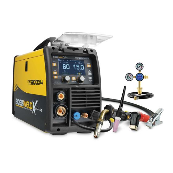
- Page 2 The BOSSWELD MST 200 X4 is the latest in IGBT multipurpose welder technology, this very portable power source enables the user to complete high quality welds in both MIG - TIG - MMA/Stick electrode applications.
-
Page 3: Table Of Contents
CONTENTS PAGE WARRANTY BOX CONTENTS WARNINGS MACHINE CARE / SAFETY INSTRUCTIONS WORK AREA SAFETY MAINTENANCE & DISPOSAL / GAS BOTTLE FRONT & REAR PANEL LAYOUT MACHINE CONTROLS PANEL & SIDE PANEL (INSIDE) DUTY CYCLE MIG SYNERGIC SETUP MIG MANUAL SETUP (GAS) 16-17 MIG MANUAL SETUP (GASLESS) MIG MANUAL SPOOL GUN SETUP (GAS) -
Page 4: Warranty
7. Use on Incorrect voltage or non authorised electrical connections and plugs 8. Use of non standard parts 9. Repair, case opening, tampering with, modifications to any part of the item by non authorised BOSSWELD repairers. This warranty covers the machine only and does not include Torches, Leads, Earth Clamps, Electrode holders, Plasma Torches, Tig Torches and any of the parts on those items unless there is a manufacturing fault. -
Page 5: Box Contents
BOSSWELD MST 200 X4 AC/DC Multi Process Inverter Welder Box Contents BOSSWELD MST 200 X4 AC/DC Multi Process Inverter Welder 3 metre BZ 24 Series MIG Torch 4 metre 17 Series TIG Torch 3 metre welding cable with electrode holder... -
Page 6: Warnings
WARNING The device and packaging material are not toys! Children must not be allowed to play with the machine and its accessories. Plastic parts and packaging are choking risks for children. • Open the packaging and remove the welder carefully. •... -
Page 7: Machine Care / Safety Instructions
MACHINE CARE / SAFETY Keep the welding cables, earth clamp and electrode holder in good condition. Failure to do this can result in poor welding quality, which could be dangerous in structural situations. Prior to use, check for breakage of parts and any other conditions that may affect operation of the welder. Any part of the welder that is damaged should be carefully checked to determine whether it will perform its intended function whilst being safe for the operator. -
Page 8: Work Area Safety
WORK AREA Ensure a clear, well lit work area with unrestricted movement for the operator. The work area should be well ventilated, as welding emits fumes which can be dangerous. Always maintain easy access to the ON/OFF switch of the welder, and the electrical mains supply. Do not expose the welder to rain and do not operate in damp or wet locations Where welding must be undertaken in environments with increased risk of electric shock, confined spaces or in the presence of flammable or explosive materials, it is important that the environment be evaluated in advance... -
Page 9: Maintenance & Disposal / Gas Bottle
IMPORTANT! - We strongly recommend that you check for gas leakage prior to operation of your machine. We recommend that you close the cylinder valve when the machine is not in use. BOSSWELD, authorised representatives or agents of BOSSWELD will not be liable or responsible for the loss of any gas. -
Page 10: Front & Rear Panel Layout
FRONT PANEL 1. Control Panel 2. Positive Output Connection Socket 3. MIG Torch Euro Connector 4. Control Socket 5. Polarity Switching Cable 6. TIG Torch Gas Connector 7. Negative Output Connection Socket REAR PANEL 8. Power Switch 9. Input Power Cable 10. -
Page 11: Machine Controls Panel & Side Panel (Inside)
CONTROL PANEL 1. Welding mode button: MIG Synergic, MIG Manual, TIG Lift, TIG HF, Stick DC, Stick AC welding mode. 2. Trigger mode button: Direct select 2T or 4T trigger mode. 3. JOB button: Press for 3s to open JOB program and press for 1s to save parameters into JOB number. -
Page 12: Duty Cycle
DUTY CYCLE: Special note: If this welders duty cycle is exceeded the welder will enter “thermal overload” which will automatically stop the welding output in order to protect, both the user and the welder. You will know the welder has gone into thermal overload when the overload error signal show on screen. -
Page 13: Mig Synergic Setup
We recommend that you close the cylinder valve when the machine is not in use. BOSSWELD authorised representatives or agents of BOSSWELD will not be liable or responsible for the loss of any gas. - Page 14 MIG SYNERGIC SETUP CONTINUE Fit the Earth lead Dinse Plug to the negative Re install tip and nozzle to torch and terminal for gas welding and then connect trim wire to the end of the nozzle. earth clamp to the work piece ensuring that the clamp makes good contact with bare metal.
- Page 15 MIG SYNERGIC SETUP CONTINUE Machine is ready to weld at optimum Turn on regulator and set gas flow to setting. If the welder is running too hot, between 10-15 L/min depending on your adjusting the left knob back a little will also welding environment.
-
Page 16: Mig Manual Setup (Gas)
We recommend that you close the cylinder valve when the machine is not in use. BOSSWELD authorised representatives or agents of BOSSWELD will not be liable or responsible for the loss of any gas. - Page 17 MIG MANUAL SETUP (GAS) CONTINUE Fit the Earth lead Dinse Plug to the negative Press Menu button and adjust knob to select terminal for gas welding and then connect MIG Manual then press knob to confirm. earth clamp to the work piece ensuring that the clamp makes good contact with bare metal.
-
Page 18: Mig Manual Setup (Gasless)
MIG MANUAL SETUP (GAS) CONTINUE To adjust functions, press parameter button, Rotate left knob to adjust wire feeding speed. rotate left knob for function selection and Rotate right knob to adjust welding voltage. rotate right knob for adjustment then press parameter button again for confirmation. - Page 19 MIG MANUAL SETUP (GASLESS) CONTINUE Plug the machine 10Amp input power lead into Ensure the polarity switching cable is the wall socket, ensuring that the power plug into negative output connection switch on the machine is in the OFF position. socket for gasless welding SETTING MACHINE POLARITY DCEN - GASLESS...
-
Page 20: Mig Manual Spool Gun Setup (Gas)
IMPORTANT! - We strongly recommend that you check for gas leakage prior to operation of your machine. We recommend that you close the cylinder valve when the machine is not in use. BOSSWELD authorised representatives or agents of BOSSWELD will not be liable or responsible for the loss of any gas. - Page 21 MIG MANUAL SPOOL GUN SETUP CONTINUED Connect earth clamp to the work piece Remove the spool cover and lift wire drive ensuring that the clamp makes good cover contact with bare metal. VIEW Fit gas regulator to the gas bottle and install Release the wire tensioning arm, and gas hose to the gas inlet on the back panel check the correct drive roller size matches...
- Page 22 MIG MANUAL SPOOL GUN SETUP CONTINUED Re install tip and nozzle to torch and trim Replace the spool cover and close the wire wire to the end of the nozzle. drive cover Press 2T/4T button to select 2T or 4T mode. Switch the machine ON using the mains 2T Mode.
-
Page 23: Mig Manual Spool Gun Setup (Gasless)
MIG MANUAL SPOOL GUN SETUP CONTINUED Ref MIG Welding Setting Guide on page 24-27 Function Setting m/min Wire Feeding Speed 1.5 ~ 16.0 Welding Voltage 10.0 ~ 27.0 Inductance 0 ~ 10 Rotate left knob to adjust wire feeding speed. Rotate right knob to adjust welding voltage. -
Page 24: Basic Mig Welding Guide
BASIC MIG WELDING GUIDE The welding power supply has two control settings that have to balance. These are voltage control switches and the wire speed control. The welding amperage is determined by the voltage settings, the wire diameter, gas selection and the wire feed speed. The amperage will increase with higher voltage selection on the machine and higher wire feed speed. - Page 25 BASIC MIG WELDING GUIDE - CONTINUE Distance from the MIG Gun Nozzle to the Work Piece The electrode stick out from the MIG gun nozzle should be between 2.0mm to 5.0mm when welding with gas shielded wire. An increased distance of 5mm to 10mm is required when welding with Gasless wire. This distance will vary depending on the type of joint that is being weld.
- Page 26 BASIC MIG WELDING GUIDE - CONTINUE SHIELDING GAS In addition to general shielding of the arc and the weld pool, the shielding gas performs a number of important functions: • forms the arc plasma • stabilises the arc roots on the material surface •...
-
Page 27: Setting Guides For Welding With Mst 200X4
SETTING GUIDE FOR WELDING WITH MST 200X4 Steel DC (+) Solid 80% Argon 20% CO 100% CO Ø 0.6mm Ø 0.8mm Ø 0.9mm Ø 1.0mm Ø 0.8mm Ø 0.9mm Ø 1.0mm m/min m/min m/min m/min m/min m/min m/min 0.8mm 14.0 14.5 1.0mm 14.8... -
Page 28: Tig Setup
TIG SET UP 6 & 7. Fit gas regulator to bottle and install gas hose to the inlet on the back panel of welder. Turn on regulator and set gas flow to between 10-15 L/min depending on your welding environment 10.Select TIG LIFT OR HF Start mode 2. - Page 29 BOSSWELD authorised representatives or agents welding current begin flowing. of BOSSWELD will not be liable or responsible for TIG HF (high frequency ignition) allows the the loss of any gas.
- Page 30 TIG SET UP - CONTINUED For NO Pulse Welding For Pulse Welding To adjust functions, press parameter button, Pulse TIG welding is most commonly used rotate left knob for function selection and to weld thin sections of stainless steel, rotate right knob for adjustment then press non-ferrous metals such as aluminum, parameter button again for confirmation.
- Page 31 TIG SET UP - CONTINUED For Spot Welding For DC Welding Spot welding is quick and easy and creates Rotate left knob to adjust welding current. a strong join. It doesn’t use any flux or filler Rotate right knob to adjust the welding voltage. metal, so there is no need to grind excess Ref AC / DC Welding Guide on page 34-35 slag when finished, and there is no dangerous...
-
Page 32: Lift Arc Start And Hr Arc Start
LIFT ARC START Lay the outside edge of the Gas Cup on With a small movement rotate the Gas Cup the work piece with the Tungsten Electrode forward so that the Tungsten Electrode 1- 2mm from the work piece. touches the work piece. Now rotate the Gas Cup in the reverse Press the button on the TIG torch direction to lift the Tungsten electrode from... -
Page 33: Tungsten Preparation & Grinding And Foot Control Option
Part No: 95.PA1209 This plug adaptor must be used with the Bossweld foot controller (P/N-660201), when used with the MST 200X4. The adaptor also allows the Bossweld TIG torches with 12 pin plugs to be used with the MST 200X4. -
Page 34: Basic Tig Welding Guide
BASIC TIG WELDING GUIDE FLUX COATING PROCESS CHARACTERISTICS In the TIG process the arc is formed between a pointed tungsten electrode and the workpiece in an inert atmosphere of argon. The small intense arc provided by the pointed electrode is ideal for high quality and precision welding. - Page 35 AC / DC WELDING - CONTINUE AC welding is also the preferred method for: • TIG welding aluminum, because the current supports welding at a higher temperature. • Making repairs on machinery because the machinery usually has a magnetized field and is older and may have rusty areas where there is concern about the higher heat penetration that can occur with DC welding.
-
Page 36: Pulse Tig Welding
PULSE TIG WELDING TIG welding with the pulse feature is most often done for thin metals such as aluminum and can also be used with copper and varieties of steel. Pulsing can be set up with a foot pedal or as a setting on your TIG welder, but when should you use pulsing? There are some very specific applications for pulsing with a TIG welder and then there are times when it can just come in handy to get a job done better. -
Page 37: Stick Ac / Dc Setup
STICK AC / DC SETUP Note: The below image shows setup for DCEP / Negative Polarity (Most Common application) 6. Select Stick AC or DC mode 2. Connect Electrode holder to the terminal 2. Connect earth Clamp to the terminal Plug the machine 10Amp input power lead into Connect earth clamp firmly to work-piece the wall socket, ensuring that the power... - Page 38 STICK AC / DC SETUP - CONTINUED Ensure the electrode / electrode holder is Rotate right knob to adjust the welding not near the work-piece or can earth out, voltage. turn the machine on using the mains power switch. The front displays will light up and Press 1 time on the right knob for the cooling fan will start.
-
Page 39: General Mma Welding Guide
MANUAL METAL ARC PROCESS (MMA WELDING) When an arc is struck between the metal rod (electrode) and the workpiece, both the rod and workpiece surface melt to form a weld pool. Simultaneous melting of the flux coating on the rod will form gas and slag which protects the weld pool from the surrounding atmosphere. -
Page 40: Set Up Of Wire Spool & Wire Feed Unit
SET UP OF WIRE SPOOL & WIRE FEED UNIT Remove the Drive Roller Cover. Check the Open the side door of the machine. Drive roller is matched to the wire size for the job. Note: Correct wire side on roller to face into machine when fitting. -
Page 41: Mig Torch Setup
MIG TORCH SET Attach the Euro Connect MIG torch to the Press the trigger. This will feed the wire machine feeding the wire into the liner. through the torch. Release button when Tighten MIG Torch conanector to machine. wire appears at the end of the torch. Re install tip over the wire and tighten Remove nozzle (A) and tip (B) from torch. -
Page 42: Mig Torch Liner Installation / Replacement
MIG TORCH LINER INSTALLATION / REPLACEMENT Lay the MIG torch out Carefully feed the new Re install tip and tighten straight and flat on the liner into the torch lead all using the tool provided and ground and remove the the way out the end of the re attach nozzle to torch. -
Page 43: Mig Torch And Consumable Care
MIG torch parts. This silicon free compound is used to prolong the life of nozzles & tips. Bossweld 8 Ways MIG Welding Pliers Handy 8 function welders pliers. Functions include, nozzle removal, tip removal, cleaning inside of nozzle... -
Page 44: List Of Error Codes
LIST OF ERROR CODES Error Type Code Description Over-heating (1st thermal relay) Over-heating (2nd thermal relay) Thermal relay Over-heating (3rd thermal relay) Over-heating (4th thermal relay) Over-heating (Program default) Phase loss No gas Welding Under voltage machine Over voltage Over current Wire feeder over load Button fault on operating panel when switch on the machine... -
Page 45: Bz 24 Mig Torch Parts Break Down
BOSSWELD BINZEL STYLE 24 MIG TORCH BZ 24 BOSSWELD BINZEL STYLE MIG TORCH COMPLETE PART NO. DESCRIPTION 92.ER.24.3 BZ Style 24 MIG Torch 3m 92.ER.24.4 BZ Style 24 MIG Torch 4m 92.ER.24.5 BZ Style 24 MIG Torch 5m BOSSWELD BINZEL STYLE 24 MIG TORCH SPARE PARTS... -
Page 46: Tig Torch Parts Breakdown
BOSSWELD 17 SERIES 150AMP & 26 SERIES 180AMP TIG TORCH COMPLETE & SPARES BACK CAP INSULATOR COLLET TORCH BODY PART NO. DESCRIPTION 95.17F.4.1.SW9A Bossweld 17 Series TIG Torch 4mt 9 pin Plug 95.17F.8.1.SW9A Bossweld 17 Series TIG Torch 8mt 9 pin Plug COLLET BODY 95.26F.4.1.SW9A... -
Page 47: Spool Gun Parts Breakdown
• mild steel and stainless steel. SPX15 SPOOL GUN NO. PART NO. DESCRIPTION 97.SPX15.4.9 Bossweld 4mt spool gun SPX15 9 pin Plug Current 180 Amps Duty Cycle 60% @ 180 Amps CO2 97.SPX15.8.9 Bossweld 8mt spool gun SPX15 9 pin Plug @ 40˚C... -
Page 48: Helpful Information & Trouble Shooting
HELPFUL INFORMATION Filler Metal Notes Solid Mild Steel wire • Use Industry standard - copper coated ER70S-6 Steel MIG Wire. This requires a shielding gas (CO2 or argon/ CO2 mix),excellent results on panel steel. Gasless Flux cored Mild Steel Wire •... - Page 49 MIG WIRE FEED TROUBLE SHOOTING The following chart addresses some of the common WIRE FEED problems during MIG welding. Issue Possible Reason Suggested Remedy No wire feed • Wrong mode selected • Check that the TIG/MMA/MIG selector switch set to MIG position Inconsistent / interrupted •...
- Page 50 TROUBLE SHOOTING Issue Possible Reason Suggested Remedy Power indicator is not lit, • Welder is not plugged into • Check that the welder is plugged into the fan does not work and no power supply 240V mains outlet and is switched on. output current •...
- Page 51 TROUBLE SHOOTING - CONTINUED Issue Possible Reason Suggested Remedy Porosity - small cavities or • Gas nozzle clogged with • Clean or replace the gas nozzle holes resulting from gas spatter, worn or out of shape pockets in weld metal •...
- Page 52 OTHER PRODUCTS IN OUR RANGE • ELECTRODES • MIG WIRE • TIG RODS • GAS EQUIPMENT • WELDING HELMETS • WELDING SAFETY • WELDING MACHINES • MIG TORCHES • TORCH SPARE PARTS • TIG TORCHES • WELDING ACCESSORIES • WELDING CABLE...
Need help?
Do you have a question about the MST 200X4 and is the answer not in the manual?
Questions and answers