Table of Contents
Advertisement
Advertisement
Table of Contents

Related Manuals for BossWeld M150


Summary of Contents for BossWeld M150
- Page 1 M150 INVERTER MIG WELDER GAS/GASLESS MANUAL YEAR LIMITED WARRANTY...
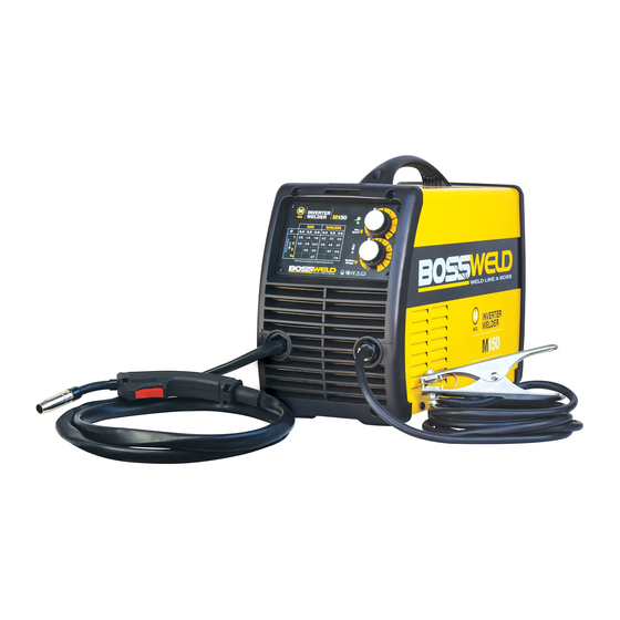
- Page 2 The BOSSWELD M-150 is the latest in IGBT Inverter welder technology; this very portable MIG welder is easy to set up, easy to use, enabling the user to complete smooth welds with both Gas and Gasless MIG wire. Ideal for around the home, DIY workshop, or rural applications.
-
Page 3: Table Of Contents
CONTENTS PAGE WARRANTY BOX CONTENTS WARNINGS MACHINE CARE / SAFETY INSTRUCTIONS WORK AREA SAFETY MAINTENANCE & DISPOSAL / GAS BOTTLE FRONT & REAR PANEL LAYOUT MACHINE INSIDE DUTY CYCLE / POWER SUPPLY WARNING WIRE FEEDER SETUP MIG TORCH SETUP GASLESS MIG WELDING SETUP 16-17 GAS MIG WELDING SETUP 18-19... -
Page 4: Warranty
7. Use on Incorrect voltage or non authorised electrical connections and plugs 8. Use of non standard parts 9. Repair, case opening, tampering with, modifications to any part of the item by non authorised BOSSWELD repairers. This warranty covers the machine only and does not include Torches, Leads, Earth Clamps, Electrode holders, Plasma Torches, Tig Torches and any of the parts on those items unless there is a manufacturing fault. -
Page 5: Box Contents
BOSSWELD M150 Inverter DC MIG Welder Box Contents BOSSWELD M150 Inverter MIG/MMA/TIG Welder 15 Series MIG Torch direct connect Welding Earth Lead direct connect Gas Hose Dual Stage Argon Regulator Cable / Lead Tidy Torch Spares Drive Roller (Installed in Machine 0.8-0.9 V Groove) - not shown. -
Page 6: Warnings
WARNING The device and packaging material are not toys! Children must not be allowed to play with the machine and its accessories. Plastic parts and packaging are choking risks for children. • Open the packaging and remove the welder carefully. •... -
Page 7: Machine Care / Safety Instructions
MACHINE CARE / SAFETY Keep the welding cables, earth clamp and electrode holder in good condition. Failure to do this can result in poor welding quality, which could be dangerous in structural situations. Prior to use, check for breakage of parts and any other conditions that may affect operation of the welder. Any part of the welder that is damaged should be carefully checked to determine whether it will perform its intended function whilst being safe for the operator. -
Page 8: Work Area Safety
WORK AREA Ensure a clear, well lit work area with unrestricted movement for the operator. The work area should be well ventilated, as welding emits fumes which can be dangerous. Always maintain easy access to the ON/OFF switch of the welder, and the electrical mains supply. Do not expose the welder to rain and do not operate in damp or wet locations Where welding must be undertaken in environments with increased risk of electric shock, confined spaces or in the presence of flammable or explosive materials, it is important that the environment be evaluated in advance... -
Page 9: Maintenance & Disposal / Gas Bottle
IMPORTANT! - We strongly recommend that you check for gas leakage prior to operation of your machine. We recommend that you close the cylinder valve when the machine is not in use. BOSSWELD, authorised representatives or agents of BOSSWELD will not be liable or responsible for the loss of any gas. -
Page 10: Front & Rear Panel Layout
FRONT PANEL 1. Wire Speed / Voltage Table 2. Power Indicator Light 3. Overload error indicator 4. Welding Speed Adjustment 5. Welding Voltage Control Knob 6. MIG Torch 7. Welding Earth Lead REAR PANEL 8. Mains Power Switch 9. Gas Input 10. -
Page 11: Machine Inside
SIDE PANEL (DOOR OPEN) A. Spool Hub B. Spool Hub Nut C. Drive Roller Cover D. Drive Roller E. Guide Tube F. Wire Feed Tensioning Knob G. Wire Tensioning Arm H. Idle Roller Inlet tube J. Wire Feed inching K Polarity Switching Terminal SETTING MACHINE POLARITY DCEN - GASLESS DCEP - GAS... -
Page 12: Duty Cycle / Power Supply Warning
DUTY CYCLE: Special note: If this welders duty cycle is exceeded the welder will enter “thermal overload” which will automatically stop the welding output in order to protect, both the user and the welder. You will know the welder has gone into thermal overload when the thermal overload light is illuminated. The welder will then cool itself down, and once the thermal overload indicator light is no longer illuminated, welding can then re-commence. -
Page 13: Wire Feeder Setup
SET UP OF WIRE SPOOL & WIRE FEED UNIT Remove the Drive Roller Cover. Check Open the side door of the machine. the Drive roller is matched to the wire Note: Correct wire side size for the job on roller to face into machine when fitting. -
Page 14: Mig Torch Setup
SET UP OF MIG TORCH Remove nozzle (A) and Re install tip over the wire and tip (B) from torch. tighten using the tool supplied, Do NOT over tighten, or you may damage the tip holder and re-attach nozzle to torch. Plug machine into 240V and switch to the ON position on the back of machine. - Page 15 MIG torch parts. This silicon free compound is used to prolong the life of nozzles & tips. Bossweld 8 Ways MIG Welding Pliers (Part No: 800074) Handy 8 function welders pliers. Functions include, nozzle removal, tip removal, cleaning inside of nozzle...
-
Page 16: Gasless Mig Welding Setup
MACHINE SET UP GASLESS MIG WELDING Plug the machine 15Amp input power lead into Set up the wire feed unit as per section the wall socket, ensuring that the power “Set up Wire Feed Unit”. switch on the machine is in the OFF position. * Gasless Drive roller has a jagged groove Correct wire side on roller to face into machine when fitting. - Page 17 MACHINE SET UP GASLESS MIG WELDING CONTINUED Re install tip and nozzle to torch and trim wire Connect earth clamp to the work piece to the end of the nozzle. ensuring that the clamp makes good contact with bare metal. Switch the machine on using the mains power switch.
-
Page 18: Gas Mig Welding Setup
MACHINE SET UP GAS MIG WELDING Plug the machine 15Amp input power lead into Ensure the polarity is correct for gas welding, the wall socket, ensuring that the power DCEP switch on the machine is in the OFF position. SETTING MACHINE POLARITY DCEN - GASLESS DCEP - GAS Correct wire side on roller to face into... - Page 19 MACHINE SET UP GAS MIG WELDING - CONTINUED Turn on regulator and set gas flow to between Remove nozzle and tip from torch and press 10-15 L/min depending on your welding the wire feed button inside the machine door, environment. this will feed the wire through the torch.
-
Page 20: General Mig Welding
BASIC MIG WELDING GUIDE The welding power supply has two control settings that have to balance. These are voltage control switches and the wire speed control. The welding amperage is determined by the voltage settings, the wire diameter, gas selection and the wire feed speed. The amperage will increase with higher voltage selection on the machine and higher wire feed speed. - Page 21 Welding Wire Selection Guide WELDING WIRE SELECTION GUIDE Carbon Steel Mig Wire, Gas Shielded Gasless, Flux Core Wire 0.6mm 0.8mm 0.9mm 1.2mm 0.8mm 0.9mm 1.2mm 30-45 45-60 50-60 60-75 70-80 50-65 70-105 90-110 90-110 70-90 75-90 120-130 120-130 90-105 95-120 135-150 135-150 110-135...
- Page 22 GMAW (MIG) WELDING Metal inert gas (MIG) welding is an attractive alternative to MMA (stick welding), offering high deposition rates and high productivity. PROCESS CHARACTERISTICS MIG welding is a versatile technique suitable for both thin sheet and thick section components. An arc is struck between the end of a wire electrode and the workpiece, melting both of them to form a weld pool.
-
Page 23: Common Wear Part
Denotes driver rollers supplies with machine BZ15 BOSSWELD BINZEL STYLE DIRECT CONNECT MIG TORCH Please note: This replacement torch must be replaced by Bossweld or an authorised service centre Failure to do so will void your machine warranty. PART NO. - Page 24 HELPFUL INFORMATION Filler Metal Notes Solid Mild Steel wire • Use Industry standard - copper coated ER70S-6 Steel MIG Wire. This requires a shielding gas (CO2 or argon/CO2 mix),excellent results on panel steel. Gasless Flux cored Mild • Use Industry standard flux cored ER71T-GS Steel MIG Wire. Steel Wire This does not require a shielding gas.
- Page 25 TROUBLE SHOOTING Issue Possible Reason Suggested Remedy Power indicator is not lit, • Welder is not plugged into • Check that the welder is plugged into the fan does not work and no power supply 240V mains outlet and is switched on. output current •...
- Page 26 • Remove materials like paint, grease, oil, and dirt, including mill scale from base metal No gas flow • Gas Regulator is off or •Check Regulator pressure too low • Something caught in the valve • Remove • Solenoid valve is damaged, • Contact BOSSWELD hotline...
- Page 27 • Contaminated MIG wire • Use clean dry rust free wire. Do not lubricate the wire with oil, grease etc. For Further Tips and Information please visit Bossweld TV Scan here to visit Bossweld TV...
- Page 28 Version 1.0 2019 OTHER PRODUCTS IN OUR RANGE • ELECTRODES • MIG WIRE • TIG RODS • GAS EQUIPMENT • WELDING HELMETS • WELDING SAFETY • WELDING MACHINES • MIG TORCHES • TORCH SPARE PARTS • TIG TORCHES • WELDING ACCESSORIES •...
Need help?
Do you have a question about the M150 and is the answer not in the manual?
Questions and answers
what welding tip fits my Boss150H dual purpose (gas- gasless ) the wire I am using is a gasless 0.9 Boss wire it appears to be a different diameter to most other tips the thread also looks a little finer
The compatible welding tip for the BossWeld M150 using gasless 0.9mm wire is the Contact Tip 0.9mm x M6.
This answer is automatically generated