Table of Contents
Advertisement
Advertisement
Table of Contents

Related Manuals for BossWeld MST195


Summary of Contents for BossWeld MST195
- Page 1 MST195 INVERTER MIG/TIG/STICK WELDER MANUAL YEAR LIMITED WARRANTY...
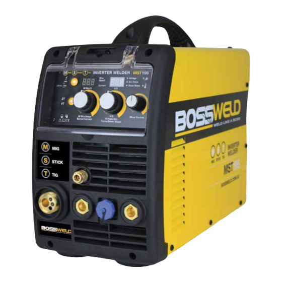
- Page 2 The BOSSWELD MST195 is the latest in IGBT welder technology, this lightweight multipurpose welder is very simple to set up and operate enabling the user to complete high quality welds in MIG Gas / Gasless and MMA / Stick electrode as well as DC TIG processes.
-
Page 3: Table Of Contents
CONTENTS PAGE WARRANTY BOX CONTENTS WARNINGS MACHINE CARE / SAFETY INSTRUCTIONS WORK AREA SAFETY MAINTENANCE & DISPOSAL / GAS BOTTLE FRONT & REAR PANEL LAYOUT MACHINE CONTROLS PANEL MACHINE INSIDE WIRE SPOOL & WIRE FEED SET UP MIG TORCH SETUP LINER INSTALATION / REPLACEMENT DRIVE ROLLER SIZE 2T / 4T TRIGGER CONTROL INFORMATION... -
Page 4: Warranty
7. Use on Incorrect voltage or non authorised electrical connections and plugs 8. Use of non standard parts 9. Repair, case opening, tampering with, modifications to any part of the item by non authorised BOSSWELD repairers. This warranty covers the machine only and does not include Torches, Leads, Earth Clamps, Electrode holders, Plasma Torches, Tig Torches and any of the parts on those items unless there is a manufacturing fault. -
Page 5: Box Contents
BOSSWELD MST195 Inverter DC MIG Welder Box Contents BOSSWELD MST195 Inverter MIG/MMA/TIG Welder 3 metre 15 Series MIG Torch Electrode Holder Lead Welding Earth Lead Gas Hose Dual Stage Argon Regulator Cable / Lead Tidy Torch Spares Drive Roller (Installed in Machine 0.8-0.9 V Groove) - not shown. -
Page 6: Warnings
WARNING The device and packaging material are not toys! Children must not be allowed to play with the machine and its accessories. Plastic parts and packaging are choking risks for children. • Open the packaging and remove the welder carefully. •... -
Page 7: Machine Care / Safety Instructions
MACHINE CARE / SAFETY Keep the welding cables, earth clamp and electrode holder in good condition. Failure to do this can result in poor welding quality, which could be dangerous in structural situations. Prior to use, check for breakage of parts and any other conditions that may affect operation of the welder. Any part of the welder that is damaged should be carefully checked to determine whether it will perform its intended function whilst being safe for the operator. -
Page 8: Work Area Safety
WORK AREA Ensure a clear, well lit work area with unrestricted movement for the operator. The work area should be well ventilated, as welding emits fumes which can be dangerous. Always maintain easy access to the ON/OFF switch of the welder, and the electrical mains supply. Do not expose the welder to rain and do not operate in damp or wet locations Where welding must be undertaken in environments with increased risk of electric shock, confined spaces or in the presence of flammable or explosive materials, it is important that the environment be evaluated in advance... -
Page 9: Maintenance & Disposal / Gas Bottle
IMPORTANT! - We strongly recommend that you check for gas leakage prior to operation of your machine. We recommend that you close the cylinder valve when the machine is not in use. BOSSWELD, authorised representatives or agents of BOSSWELD will not be liable or responsible for the loss of any gas. -
Page 10: Front & Rear Panel Layout
FRONT PANEL 1. Control Panel - See page 11 2. Euro Torch Connection Socket 3. Positive Output Connection Socket 4. Negative Output Connection Socket 5. Tig Torch Control Socket 6. Gas Output (for TIG process) REAR PANEL 7. Mains Power Switch 8. -
Page 11: Machine Controls Panel
CONTROL PANEL Welding Method Voltage , Arc Force and Downslope Display Press to select MIG / MMA Stick / TIG • Displays the Welding voltage when machine Welding Mode is in MIG • Press to select 2T or 4T • Displays the Arc Force when machine welding mode (MIG / TIG) is in Stick / MMA... -
Page 12: Machine Inside
SIDE PANLE (DOOR OPEN) A. Spool Hub B. Spool Hub Nut C. Burn back Adjustment D. Polarity Switching Terminal E. Drive Roller F. Drive Roller Retainer Nut G. Wire Inlet H. Wire Guide Inlet Tube Wire Feed Tensioning Adjustment J. Idle Roller / Wire Tensioning Arm SETTING MACHINE POLARITY DCEN - GASLESS DCEP - GAS... -
Page 13: Wire Spool & Wire Feed Set Up
SET UP OF WIRE SPOOL & WIRE FEED UNIT Remove the Drive Roller Cover. Check Open the side door of the machine. the Drive roller is matched to the wire size for the job Note: Correct wire side on roller to face into machine when fitting. -
Page 14: Mig Torch Setup
SET UP OF MIG TORCH Attach the Euro Connect MIG Press the trigger. This will feed torch to the machine fedding the the wire through the torch. wire into the liner. Release button when wire appears at the end of the torch. Tighten MIG Torch connector to machine. -
Page 15: Liner Instalation / Replacement
MIG TORCH LINER INSTALLATION / REPLACMENT Re install tip and tighten Carefully feed the new Lay the MIG torch out using the tool provided liner into the torch lead all straight and flat on the and re attach nozzle to the way out the end of the ground and remove the torch. -
Page 16: Drive Roller Size
MACHINE DRIVE ROLLER SIZE (NOTE: MACHINE WILL RUN UP TO 1.0MM WIRE) PART No: DESCRIPTION Knurled Drive Roller For Gasless Wire RK302210.08.10 Drive Roller 0.8/1.0mm Knurled 30 x 22 x 10mm 10mm RK302210.09.12 Drive Roller 0.9/1.2mm Knurled 30 x 22 x 10mm RK302210.10.12 Drive Roller 1.0/1.2mm Knurled 30 x 22 x 10mm 30mm... -
Page 17: Lift Arc Start
LIFT ARC START Lay the outside edge of the Gas Cup on the With a small movement rotate the Gas Cup work piece with the Tungsten Electrode forward so that the Tungsten Electrode 1- 2mm from the work piece. touches the work piece. Now rotate the Gas Cup in the reverse Press the button on the TIG torch direction to lift the Tungsten electrode from the... -
Page 18: Mig Torch And Consumable Care
MIG torch parts. This silicon free compound is used to prolong the life of nozzles & tips. Bossweld 8 Ways MIG Welding Pliers Handy 8 function welders pliers. Functions include, nozzle removal, tip removal, cleaning inside of nozzle... -
Page 19: Sitck / Mma Welding Setup
MACHINE SET UP STICK/MMA Note: The below image shows setup for DCEP / Negative Polarity (Most Common application) 6.Select Stick / MMA mode 3. Connect earth Clamp to the terminal 2. Connect Electrode holder to the terminal Plug the machine 15Amp input power lead into Connect earth clamp firmly to work-piece the wall socket, ensuring that the power ensuring that the clamp makes good contact... - Page 20 MACHINE SET UP STICK/MMA - CONTINUED Ensure the electrode/electrode holder is not You can adjust the Arc force by using voltage near the work-piece or can earth out, turn the Parameter adjustment knob. machine on using the mains power switch. The front displays will light up and the cooling fan will start.
-
Page 21: General Mma Welding
MANUAL METAL ARC PROCESS (MMA WELDING) When an arc is struck between the metal rod (electrode) and the workpiece, both the rod and workpiece surface melt to form a weld pool. Simultaneous melting of the flux coating on the rod will form gas and slag which protects the weld pool from the surrounding atmosphere. -
Page 22: Gasless Mig Welding Setup
MACHINE SET UP GASLESS MIG WELDING 8.Select MIG mode 4. Connect Mig Torch to the Euro Connection terminal NOTE: Ensure connector nut is tighten firmly 6. Connect earth Clamp to the terminal Plug the machine 15Amp input power lead Set up the wire feed unit as per section “Set into the wall socket, e nsuring that the power up Wire Feed Unit”. - Page 23 MACHINE SET UP GASLESS MIG WELDING CONTINUED Ensure the polarity is correct for gasless Press the Welding Mode Selection Button until welding, DCEN the MIG indicator is lit. SETTING MACHINE POLARITY DCEN - GASLESS DCEP - GAS Remove nozzle and tip from torch and press trigger on the welding torch, this will feed the wire through the torch.
-
Page 24: Gas Mig Welding Setup
We recommend that you close the cylinder valve when the machine is not in use. BOSSWELD authorised representatives or agents of BOSSWELD will not be liable or responsible for the loss of any gas. - Page 25 MACHINE SET UP GASLESS MIG WELDING CONTINUED Plug the machine 15Amp input power lead Install Euro connect MIG torch over the into the wall socket, ensuring that the power protruding wire, line up the spring connectors switch on the machine is in the OFF position. and screw the Euro connector nut up firmly.
- Page 26 MACHINE SET UP GAS MIG WELDING CONTINUED Re install tip and nozzle to torch and trim wire Switch the machine on using the mains power to the end of the nozzle. The multifunction switch. Wait a few seconds whilst the machine digital display will show two numbers.
- Page 27 MACHINE SET UP GAS MIG WELDING CONTINUED Fit gas regulator to the gas bottle and install gas hose to the gas inlet on the back panel of welder. Turn on regulator and set gas flow to between 10-15 L/min depending on your welding environment.
-
Page 28: General Mig Welding
BASIC MIG WELDING GUIDE The welding power supply has two control settings that have to balance. These are voltage control switches and the wire speed control. The welding amperage is determined by the voltage settings, the wire diameter, gas selection and the wire feed speed. The amperage will increase with higher voltage selection on the machine and higher wire feed speed. - Page 29 Welding Wire Selection Guide WELDING WIRE SELECTION GUIDE Carbon Steel Mig Wire, Gas Shielded Gasless, Flux Core Wire 0.6mm 0.8mm 0.9mm 1.2mm 0.8mm 0.9mm 1.2mm 30-45 45-60 50-60 60-75 70-80 50-65 70-105 90-110 90-110 70-90 75-90 120-130 120-130 90-105 95-120 135-150 135-150 110-135...
- Page 30 MIG WELDING SETTING GUIDES Welding current Welding Volt Wave control Wire Speed (Wire Size) 0.6mm 0.8mm 1.0mm 13~15V 2--3 14~16V 3--5 2--3 15~17V 6--8 3--5 2--3 100A 16~19V 8--10 3--6 120A 17~20V 4--7 3--5 140A 19~21V 5-10 5--8 3--5 160A 20~22V 5-10 6--9...
- Page 31 GMAW (MIG) WELDING CONTINUED SHIELDING GAS In addition to general shielding of the arc and the weld pool, the shielding gas performs a number of important functions: • forms the arc plasma • stabilises the arc roots on the material surface •...
-
Page 32: Tig Welding Setup
We strongly recommend that you check for gas leakage prior to operation of your machine. We recommend that you close the cylinder valve when the machine is not in use. BOSSWELD authorised representatives or agents of BOSSWELD will not be liable or responsible for the loss of any gas. - Page 33 MACHINE SET UP TIG WELD - CONTINUED Fit the Earth lead Dinse Plug to the positive To adjust the Welding Current rotate the knob terminal for gasless welding and then connect to the desired Amperage. earth clamp to the work piece ensuring that the clamp makes good contact with bare metal.
-
Page 34: Tungsten Preperation
WORK PIECE WORK PIECE WORK PIECE WORK PIECE TUNGSTEN PREPARATION & GRINDING Grinding creates the greatest hazard as the exposed tungsten/thoria area is greatly increased and fine particles of potentially radioactive dust are released into the atmosphere. It is recommended that a dedicated grindstone with local dust extraction is used, and a simple filter mask is worn. -
Page 35: General Tig Welding
WORK PIECE WORK PIECE TIG WELDING - CONTINUED This risk can be minimised using the ‘lift arc’ technique where the short-circuit is formed at a very low current level. The most common way of starting the TIG arc is to use HF (High Frequency). HF consists of FLUX COATING high voltage sparks of several thousand volts which last for a few microseconds. -
Page 36: Bz15 Mig Torch Parts Break Down
BZ15 BOSSWELD BINZEL STYLE MIG TORCH COMPLETE PART NO. DESCRIPTION 92.ER.15.3 BZ Style 15 MIG Torch 3m 92.ER.15.4 BZ Style 15 MIG Torch 4m 92.ER.15.5 BZ Style 15 MIG Torch 5m TRIGGER HANDLE GAS HOLDER INSULATOR SPRING CONTACT TIP GAS NOZZLE... -
Page 37: Tig Torch Breakdown
BOSSWELD 26 SERIES 200AMP TIG TORCH COMPLETE PART NO. DESCRIPTION 95.26.4.1.SW.DA50 Tig Torch 26, 4mt, 1 pc, Switch, Dinse 50 95.26.8.1.SW.DA50 Tig Torch 26, 8mt, 1 pc, Switch, Dinse 50 BACK CAP FLEX TORCH BODY INSULATOR COLLET TORCH BODY COMPACT INSULATOR... -
Page 38: Helpful Information & Trouble Shooting
HELPFUL INFORMATION Filler Metal Notes Solid Mild Steel wire • Use Industry standard - copper coated ER70S-6 Steel MIG Wire. This requires a shielding gas (CO2 or argon/CO2 mix),excellent results on panel steel. Gasless Flux cored Mild • Use Industry standard flux cored ER71T-GS Steel MIG Wire. Steel Wire This does not require a shielding gas. - Page 39 TROUBLE SHOOTING Issue Possible Reason Suggested Remedy Power indicator is not lit, • Welder is not plugged into • Check that the welder is plugged into the fan does not work and no power supply 240V mains outlet and is switched on. output current •...
- Page 40 • Remove materials like paint, grease, oil, and dirt, including mill scale from base metal No gas flow (TIG) • Gas Regulator is off or Check Regulator pressure too low • Something caught in the valve • Remove • Solenoid valve is damaged, • Contact BOSSWELD hotline...
- Page 41 MIG WIRE FEED TROUBLE SHOOTING The following chart addresses some of the common WIRE FEED problems during MIG welding. Issue Possible Reason Suggested Remedy No wire feed • Wrong mode selected • Check that the TIG/MMA/MIG selector switch set to MIG position Inconsistent / interrupted •...
- Page 44 OTHER PRODUCTS IN OUR RANGE • ELECTRODES • MIG WIRE • TIG RODS • GAS EQUIPMENT • WELDING HELMETS • WELDING SAFETY • WELDING MACHINES • MIG TORCHES • TORCH SPARE PARTS • TIG TORCHES • WELDING ACCESSORIES • WELDING CABLE...
Need help?
Do you have a question about the MST195 and is the answer not in the manual?
Questions and answers