
Related Manuals for BossWeld POWERPULSE 250


Summary of Contents for BossWeld POWERPULSE 250
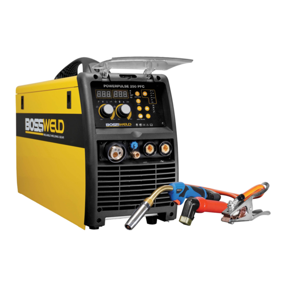
- Page 1 POWERPULSE 250 DUAL PULSE SYNERGIC MST INVERTER WELDER MANUAL YEAR LIMITED WARRANTY...
- Page 2 , improve the quality of welding process . Arc welding with the POWERPULSE 250 machine t is suitable for all positions welding for various plates made of stainless steel, carbon steel, alloyed steel etc. Applications applied to pipe installment, petrochemical, architecture equipment, car repair, bicycle repair, handicraft and common steel fabrication.
-
Page 3: Table Of Contents
CONTENTS PAGE WARRANTY BOX CONTENTS WARNINGS MACHINE CARE / SAFETY INSTRUCTIONS WORK AREA SAFETY MAINTENANCE & DISPOSAL / GAS BOTTLE FRONT & REAR PANEL LAYOUT MACHINE INSIDE MACHINE CONTROLS PANEL 14-18 DUAL PULSE FUNCTION WIRE SPOOL & WIRE FEED SET UP MIG TORCH SETUP LINER INSTALLATION / REPLACEMENT DRIVE ROLLER SIZE... -
Page 4: Warranty
7. Use on Incorrect voltage or non authorised electrical connections and plugs 8. Use of non standard parts 9. Repair, case opening, tampering with, modifications to any part of the item by non authorised BOSSWELD repairers. This warranty covers the machine only and does not include Torches, Leads, Earth Clamps, Electrode holders, Plasma Torches, Tig Torches and any of the parts on those items unless there is a manufacturing fault. -
Page 5: Box Contents
BOSSWELD POWERPULSE 250PFC Inverter MIG/MMA Welder Box Contents BOSSWELD POWERPULSE 250PFC Inverter DC MIG Welder 3 metre 36 Series MIG Torch Welding cable with electrode holder Earth cable with earth clamp Gas Hose Dual Stage Argon Regulator Torch Spares Carry Strap Drive Roller (spare –... - Page 6 ELECTRIC SHOCK CAN KILL. Touching live electrical parts can cause fatal shocks or severe burns. The electrode and work circuit is electrically live whenever the output is on. The input power circuit and internal machine circuits are also live when power is on. In Mig/Mag welding, the wire, drive rollers, wire feed housing, and all metal parts touching the welding wire are electrically live.
- Page 7 • Sparks and spatter are thrown from the welding arc. Wear oil free protective garments such as leather gloves, heavy shirt, cuff less trousers, high shoes and a cap over your hair. Wear earplugs when welding out of position or in confined places. Always wear safety glasses with side shields when in a welding area.
-
Page 8: Warnings
WARNING The device and packaging material are not toys! Children must not be allowed to play with the machine and its accessories. Plastic parts and packaging are choking risks for children. • Open the packaging and remove the welder carefully. •... -
Page 9: Machine Care / Safety Instructions
MACHINE CARE / SAFETY Keep the welding cables, earth clamp and electrode holder in good condition. Failure to do this can result in poor welding quality, which could be dangerous in structural situations. Prior to use, check for breakage of parts and any other conditions that may affect operation of the welder. Any part of the welder that is damaged should be carefully checked to determine whether it will perform its intended function whilst being safe for the operator. -
Page 10: Work Area Safety
WORK AREA Ensure a clear, well lit work area with unrestricted movement for the operator. The work area should be well ventilated, as welding emits fumes which can be dangerous. Always maintain easy access to the ON/OFF switch of the welder, and the electrical mains supply. Do not expose the welder to rain and do not operate in damp or wet locations Where welding must be undertaken in environments with increased risk of electric shock, confined spaces or in the presence of flammable or explosive materials, it is important that the environment be evaluated in advance... -
Page 11: Maintenance & Disposal / Gas Bottle
IMPORTANT! - We strongly recommend that you check for gas leakage prior to operation of your machine. We recommend that you close the cylinder valve when the machine is not in use. BOSSWELD, authorised representatives or agents of BOSSWELD will not be liable or responsible for the loss of any gas. - Page 12 FRONT PANEL 1. Control Panel 2. Positive Output Connection Socket 3. Remote Connection Plug (9pin) 4. Euro Torch Connection 5. Quick Connect Gas Valve 6. Negative Output Connection Socket REAR PANEL 7. Mains Power Switch 8. Water Cooling connector 9. Gas Input 10.
- Page 13 SIDE PANEL (DOOR OPEN) 12. Spool Holder 13. Wire Feed Tensioning Adjustment 14. Wire Tension Arm and Support Roller 15. Wire Inlet 16. Drive Roller 17. Drive Roller Retainer Nut 18. Wire Feed Motor 19. MIG Torch Polarity Change SETTING MACHINE POLARITY DCEN - GASLESS DCEP - GAS NOTE:...
- Page 14 SPOOL SPOOL SYNERGIC PROGRAMS INDICATOR Select from a list of Preset programs, This will set the machine for the correct wire size, wire type and gas being used, Program number will be displayed to the left digital display SPOOL WELDING VOLTS INDICATOR Value will be displayed on the left digital display.
- Page 15 SPOOL WIRE INCH BUTTON Press and hold to feed wire GAS CHECK BUTTON Press and hold to check gas flow SPOOL WELDING PROCESS BUTTON - MIG-MAG Pulse Synergic - MIG-MAG Dual Pulse Synergic SPOOL - MIG-MAG Manual - MIG-MAG Synergic - MMA - TIG SPOOL...
- Page 16 FUNCTION BUTTON Press to scroll through weld function settings Parameters will be displayed to both digital display See below for function settings PRE GAS Selection for gas flow time prior to the arc starting Adjustable from 0 - 5 sec SPOOL POST GAS Selection for gas flow time after the arc finishes.
- Page 17 START CURRENT PERCENT In 4T trigger mode, sets a welding current 10-200% of the main welding current activated when the trigger is held on to ‘latch’ the trigger before SPOOL the main weld current is started. When trigger is released, the current will go through the upslope period if it is set, to the main welding current Adjustable from 10 - 200% START CURRENT ARC LENGTH...
- Page 18 JOB SAVE - SPOOL Set Job parameters (welding function, welding mode, welding parameters, etc) Press The JOB button and display will show SPOOL SPOOL SPOOL Use the R adjustment knob to select a job number that is not being used this will be indicated by - - - on the left digital display, job number is displayed on the right digital display SPOOL Press the Save button...
-
Page 19: Dual Pulse Function
Dual pulse function introduction Dual pulse welding in single pulse welding with low frequency modulated pulse, low frequency pulse frequency 0.5-3.0Hz. Single pulse compared to dual pulse has the advantages of: without welding swing, weld automatic fish squamous and fish scale pattern density, the depth can be adjusted; to be more precise control of heat input. During the low current, cooling the molten pool, reduce workpiece deformation, reduce the hot cracking tendency;... - Page 20 MMA FUNCTION - FRONT PANEL DESCRIPTION SPOOL PANEL DESCRIPTION Hot Start / Arc Force Parameter Code Display. Welding Current. Welding amperage Indicator Light. MMA Function Select. Hot Start / Arc force Parameter Select press to Enter and Exit. Hot Start / Arc force Code Select turn Knob Left or Right. Welding Current / Hot Start / Arc force, Turn Knob Left or Right to set to desired setting.
- Page 21 IMPORTANT! - We strongly recommend that you check for gas leakage prior to operation of your machine. We recommend that you close the cylinder valve when the machine is not in use. BOSSWELD authorised representatives or agents of BOSSWELD will not be liable or responsible for the loss of any gas.
- Page 22 SET UP OF WIRE SPOOL & WIRE FEED UNIT Remove the Drive Roller Cover. Check Open the side door of the machine. the Drive roller is matched to the wire size for the job Note: Correct wire side on roller to face into machine when fitting.
- Page 23 VOLTAGE AMPERAGE CO ₂ SET UP OF MIG TORCH WIRE FLUX MODE SYNERGIC MODE V+/- M/min MANUAL • HOT START TRIGGER • ARC FORCE CHECK INDUCTANCE DS190 WIRE DIGITAL SYNERGIC INCH SYNERGIC MANUAL WELD % Adjustment +/- Voltage / Wire Speed MODE ADJUSTMENT VOLTAGE...
- Page 24 MIG TORCH LINER INSTALLATION / REPLACMENT Re install tip and tighten Carefully feed the new Lay the MIG torch out using the tool provided liner into the torch lead all straight and flat on the and re attach nozzle to the way out the end of the ground and remove the torch.
- Page 25 MACHINE DRIVE ROLLER SIZE (NOTE: MACHINE WILL RUN UP TO 1.0MM WIRE) PART NO. DESCRIPTION Knurled Drive Roller For Gasless Wire 10mm Drive Roller 0.8/0.9mm Knurled 30 x 10 x 10mm RK301010.08.09 30mm U Grooved Drive Roller For Aluminium Wire RU301010.06.08 Drive Roller 0.6/0.8mm U Groove 30 x 10 x 10mm RU301010.09.12...
- Page 26 MIG torch parts. This silicon free compound is used to prolong the life of nozzles & tips. Bossweld 8 Ways MIG Welding Pliers Handy 8 function welders pliers. Functions include, nozzle removal, tip removal, cleaning inside of nozzle...
- Page 27 MANUAL METAL ARC PROCESS (MMA WELDING) When an arc is struck between the metal rod (electrode) and the workpiece, both the rod and workpiece surface melt to form a weld pool. Simultaneous melting of the flux coating on the rod will form gas and slag which protects the weld pool from the surrounding atmosphere.
-
Page 28: Drive Roller Size
MACHINE SET UP GASLESS MIG WELDING 8.Select MIG mode 4. Connect Mig Torch to the Euro Connection terminal NOTE: Ensure connector nut is tighten firmly 6. Connect earth Clamp to the terminal Plug the machine 15Amp input power lead Set up the wire feed unit as per section “Set into the wall socket, e nsuring that the power up Wire Feed Unit”. - Page 29 MACHINE SET UP GASLESS MIG WELDING CONTINUED VOLTAGE AMPERAGE CO ₂ WIRE FLUX MODE SYNERG MODE V+/- M/min MANUAL • HOT START TRIGGER • ARC FORCE CHECK INDUCTANCE 190S WIRE INCH SYNERGIC MANUAL WELD % Adjustment +/- Voltage / Wire Speed MODE ADJUSTMENT Ensure the polarity is correct for gasless...
- Page 30 We recommend that you close the cylinder valve when the machine is not in use. BOSSWELD authorised representatives or agents of BOSSWELD will not be liable or responsible for the loss of any gas.
- Page 31 MACHINE SET UP GAS MIG WELDING CONTINUED Plug the machine 15Amp input power lead Install Euro connect MIG torch over the into the wall socket, ensuring that the power protruding wire, line up the spring connectors switch on the machine is in the OFF position. and screw the Euro connector nut up firmly.
- Page 32 MACHINE SET UP GAS MIG WELDING CONTINUED Re install tip and nozzle to torch and trim wire Switch the machine on using the mains power to the end of the nozzle. The multifunction switch. Wait a few seconds whilst the machine digital display will show two numbers.
- Page 33 We recommend that you close the cylinder valve when the machine is not in use. BOSSWELD authorised representatives or agents of BOSSWELD will not be liable or responsible for the loss of any gas.
- Page 34 BASIC MIG WELDING GUIDE The welding power supply has two control settings that have to balance. These are voltage control switches and the wire speed control. The welding amperage is determined by the voltage settings, the wire diameter, gas selection and the wire feed speed. The amperage will increase with higher voltage selection on the machine and higher wire feed speed.
- Page 35 Welding Wire Selection Guide WELDING WIRE SELECTION GUIDE Carbon Steel Mig Wire, Gas Shielded Gasless, Flux Core Wire 0.6mm 0.8mm 0.9mm 1.2mm 0.8mm 0.9mm 1.2mm 30-45 45-60 50-60 60-75 70-80 50-65 70-105 90-110 90-110 70-90 75-90 120-130 120-130 90-105 95-120 135-150 135-150 110-135...
- Page 36 MIG WELDING SETTING GUIDES Welding current Welding Volt Wave control Wire Speed (Wire Size) 0.6mm 0.8mm 1.0mm 13~15V 2--3 14~16V 3--5 2--3 15~17V 6--8 3--5 2--3 100A 16~19V 8--10 3--6 120A 17~20V 4--7 3--5 140A 19~21V 5-10 5--8 3--5 160A 20~22V 5-10 6--9...
- Page 37 GMAW (MIG) WELDING CONTINUED SHIELDING GAS In addition to general shielding of the arc and the weld pool, the shielding gas performs a number of important functions: • forms the arc plasma • stabilises the arc roots on the material surface •...
-
Page 38: Tig Welding Setup
WORK PIECE WORK PIECE WORK PIECE WORK PIECE TUNGSTEN PREPARATION & GRINDING Grinding creates the greatest hazard as the exposed tungsten/thoria area is greatly increased and fine particles of potentially radioactive dust are released into the atmosphere. It is recommended that a dedicated grindstone with local dust extraction is used, and a simple filter mask is worn. - Page 39 TIG WELDING - CONTINUED This risk can be minimised using the ‘lift arc’ technique where the short-circuit is formed at a very low current level. The most common way of starting the TIG arc is to use HF (High Frequency). HF consists of FLUX COATING high voltage sparks of several thousand volts which last for a few microseconds.
- Page 40 BZ24 BOSSWELD BINZEL STYLE MIG TORCH COMPLETE PART NO. DESCRIPTION 92.ER.24.3 BZ Style 24 MIG Torch 3m 92.ER.24.4 BZ Style 24 MIG Torch 4m 92.ER.24.5 BZ Style 24 MIG Torch 5m M6 Standard Duty M6 Heavy Duty M6 Aluminium PART NO.
- Page 41 BOSSWELD 26 SERIES 200AMP TIG TORCH SPARE PARTS PART NO. DESCRIPTION 95.26.4.1.SW.DA50 Tig Torch 26, 4mt, 1 pc, Switch, Dinse 50 95.26.8.1.SW.DA50 Tig Torch 26, 8mt, 1 pc, Switch, Dinse 50 BACK CAP 95.26F.4.1.SW.DA50 Tig Torch 26 Flex, 4mt, 1pc, Switch, Dinse 50 95.26F.8.1.SW.DA50...
- Page 42 HELPFUL INFORMATION Filler Metal Notes Solid Mild Steel wire • Use Industry standard - copper coated ER70S-6 Steel MIG Wire. This requires a shielding gas (CO2 or argon/CO2 mix),excellent results on panel steel. Gasless Flux cored Mild • Use Industry standard flux cored ER71T-GS Steel MIG Wire. Steel Wire This does not require a shielding gas.
- Page 43 TROUBLE SHOOTING Issue Possible Reason Suggested Remedy Power indicator is not lit, • Welder is not plugged into • Check that the welder is plugged into the fan does not work and no power supply 240V mains outlet and is switched on. output current •...
- Page 44 TROUBLE SHOOTING - CONTINUED Issue Possible Reason Suggested Remedy Porosity - small cavities or • Gas nozzle clogged with • Clean or replace the gas nozzle holes resulting from gas spatter, worn or out of shape pockets in weld metal •...
- Page 45 MIG WIRE FEED TROUBLE SHOOTING The following chart addresses some of the common WIRE FEED problems during MIG welding. Issue Possible Reason Suggested Remedy No wire feed • Wrong mode selected • Check that the TIG/MMA/MIG selector switch set to MIG position Inconsistent / interrupted •...
- Page 46 OPERATIONAL ENVIRONMENT • Height above sea level ≤1000m • Operation temperature range -10°C ~ +40°C • Air relative humidity is below 90%( 20°C) • Preferably site the machine above floor level, ensure the maximum angle does not exceed 15 degrees. •...
- Page 48 OTHER PRODUCTS IN OUR RANGE • ELECTRODES • MIG WIRE • TIG RODS • GAS EQUIPMENT • WELDING HELMETS • WELDING SAFETY • WELDING MACHINES • MIG TORCHES • TORCH SPARE PARTS • TIG TORCHES • WELDING ACCESSORIES • WELDING CABLE...
Need help?
Do you have a question about the POWERPULSE 250 and is the answer not in the manual?
Questions and answers