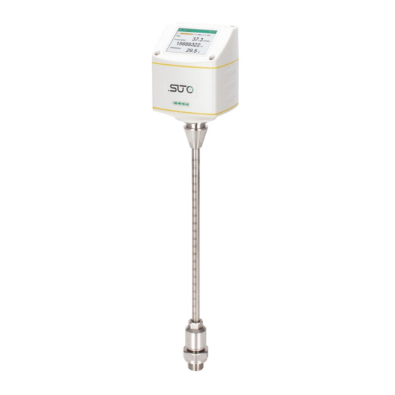
Table of Contents
Advertisement
Advertisement
Table of Contents

Summarization of Contents
1 Safety instructions
General safety instructions
General safety guidelines and warnings for product operation, installation, and maintenance.
Storage and transportation
Guidelines for storing and transporting the sensor to maintain its condition and prevent damage.
6 Technical data
6.1 General
Overview of general specifications including measurement medium, reference conditions, and housing materials.
6.2 Electrical data
Details on power supply requirements and electrical characteristics of the sensor.
6.3 Output signals
Description of the available output signals such as analog, pulse, Modbus, and M-Bus.
6.4 Accuracy
Information regarding the sensor's measurement accuracy, stated accuracy, and repeatability.
6.5 Volumetric flow ranges
Table detailing the volumetric flow measurement ranges for different pipe diameters and sensor models.
8 Determining the installation point
8.1 Reserving inlet and outlet sections
Recommendations for upstream and downstream pipe lengths to ensure accurate flow measurement.
9 Sensor installation
9.1 Installation requirements
Specifies the necessary conditions and tools for installing the flow sensor correctly.
9.2 Installation procedure
Step-by-step guide for the correct installation of the sensor into the pipe.
9.3 Electrical connection
Details on how to connect the sensor electrically, including pin assignments and connector types.
10 Sensor signal outputs
10.1 Analog output
Explanation of the 4-20 mA analog output signal and its scaling capabilities.
10.2 Pulse output
Description of the pulse output signal, its relation to consumption units, and pulse length dependency.
10.3 Modbus output
Configuration parameters and register table for Modbus communication (RTU and TCP).
10.4 M-Bus output
Communication parameters and value registers for the M-Bus interface.
11 Sensor display (optional)
11.1 Starting process
Describes the sensor display's initialization sequence and the display of online values.
11.2 Configuration using the display
Guide on how to change sensor settings like pipe diameter, gas type, and flow unit via the display.
16 Appendix A - Modbus communication example
03 (0x03) Read holding register
Details the Modbus request and response structure for reading holding registers.
05 (0x05) Write single coil
Details the Modbus request and response structure for writing a single coil.
16 (0x10) Write multiple registers
Details the Modbus request and response structure for writing multiple registers.
17 (0x11) Report slave ID
Details the Modbus request and response structure for reporting slave ID.


Need help?
Do you have a question about the S401-M and is the answer not in the manual?
Questions and answers