Table of Contents
Advertisement
Quick Links
Advertisement
Table of Contents

Related Manuals for SUTO S211


Summary of Contents for SUTO S211
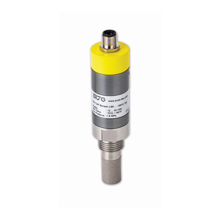
- Page 1 English Instruction and operation manual S211 / S215 / S220 Dew point sensor...
- Page 2 The device is destined exclusively for the described application. SUTO offers no guarantee for the suitability for any other purpose. SUTO is also not liable for consequential damage resulting from the delivery, capability or use of this device.
-
Page 3: Table Of Contents
9.1 Analog output ..............19 9.1.1 Scaling.................19 9.2 Modbus RTU output .............19 9.2.1 Holding Register table for Modbus RTU ......20 10 Optional accessories..............22 10.1 Measuring chambers ............22 10.2 Service kit.................22 11 Calibration................23 12 Maintenance................23 13 Disposal or waste..............23 S211 / S215 / S220... -
Page 4: Safety Instructions
• Consider all regulations for electrical installations. • The system must be disconnected from any power supply during maintenance work. • Any electrical work on the system is only allowed by authorized qualified personal. S211 / S215 / S220... - Page 5 • Please make sure that the storage temperature of the sensor is between -20 ... +50°C. • Avoid direct UV and solar radiation during storage. • For the storage the humidity must be <95% rH, no condensation. S211 / S215 / S220...
-
Page 6: Registered Trademarks
Registered trademark of SUTO iTEC MODBUS ® Registered trademark of the Modbus Organization, Hopkinton, USA HART ® Registered trademark of the HART Communication Foundation, Austin, PROFIBUS ® Registered trademark of the PROFIBUS User Organization, Karlsruhe, Germany S211 / S215 / S220... -
Page 7: Application
3 Application 3 Application The S211 / S215 / S220 are three industrial dew point sensors designed for measuring dew point and related parameters in compressed air or industrial gases under specified operating conditions (See next page ). Parameter Default unit Temperature °C... -
Page 8: Technical Data
0 ... +50°C Ambient humidity 0 ... 95% rH Operating pressure -0.1 ... 1.6 MPa -0.1 ... 35.0 MPa optional for S215 / S211 Casing material Casing: Aluminium alloy Process thread: Stainless steel 1.4301 (SUS S211 / S215 / S220... -
Page 9: Electrical Data
Screwing thread G ½” thread (ISO 228/1) Weight 0.2 kg * For CO , the measurement range of S211 is limited to -40°C Td ** The rotation force cannot exceed 3.0 N.m 5.2 Electrical data Power supply 15 ... 30 VDC Current consumption 2-wire: 4 ... -
Page 10: Accuracy
+/- 3 °C Td (-100 ... -60°C Td) Temperature: ± 0.3°C Pressure: 0.5% FS Repeatability of dew point ± 0.5°C Stated accuracy at Ambient/process temperature 23°C ± 3°C Ambient/process humidity <95% rH, no condensation Airflow > 2 l/min at sensor tip S211 / S215 / S220... -
Page 11: Dimensional Drawing
6 Dimensional drawing 6 Dimensional drawing S211 / S215 / S220... - Page 12 6 Dimensional drawing S211 / S215 / S220...
-
Page 13: Determination Of The Installation Point
• The sensor is for indoor use only! At an outdoor installation, the sensor must be protected from solar radiation and rain. • It is strongly recommend not to install S211 / S215 / S220 permanently in wet environment, which usually exists right after a compressor outlet. -
Page 14: Installation
The flowing air or gas must pass the sensor tip for a proper measurement. This can be realized with a measurement chamber. For an installation without the measuring chamber, you must insert the sensor to the required depth, as described in section 8.2. S211 / S215 / S220... -
Page 15: Installation Procedure
• Please check the size of the nozzle and make sure not less than 1/3 of the sensor tip is inside of the pipe. • The inner thread must be G 1/2”. S211 / S215 / S220... - Page 16 An upside down installation is not permitted. Removal of the sensor Unscrew the sensor off the measurement chamber or from the nozzle. Please make sure that the system is pressure-less before the sensor is removed. S211 / S215 / S220...
-
Page 17: Electrical Connection
Sensor models: S699 3215 / S699 3211 / S699 3220 Output signal: 3-wire Analog output and Modbus RTU Pin 1 Pin 2 Pin 3 Pin 4 Pin 5 4 … 20 mA Modbus RTU Modbus RTU brown white blue black grey S211 / S215 / S220... - Page 18 Active 4 … 20 mA signal Negative supply voltage Not applicable Positive supply voltage Modbus RTU data + Modbus RTU data - ATTENTION! Do not screw the M12 plug using force. Otherwise, it may damage the connecting pins. S211 / S215 / S220...
-
Page 19: Signal Outputs
Response delay : 0 ms Inter-frame spacing : 7 char Remark: If your application needs other settings, please state it in the order or use the Service Kit to configure the sensor settings on site. S211 / S215 / S220... -
Page 20: Holding Register Table For Modbus Rtu
Temperature 2300 Status INT16U 2-Byte 2301 Channel Value of FLOAT 4-Byte Dew point 2303 Channel Value of FLOAT 4-Byte Alternative humidity 2305 Channel Value of FLOAT 4-Byte Pressure 2307 Channel Value of FLOAT 4-Byte Temperature S211 / S215 / S220... - Page 21 1: This measuring channel is not working properly. 0: The 4th measuring channel that follows the Status channel (addressed 2307) is working properly. 1: This measuring channel is not working properly. Not used … S211 / S215 / S220...
- Page 22 9 Signal outputs S211 / S215 / S220...
-
Page 23: Optional Accessories
Please make sure that either the dew point sensor or the service kit is connected to the power supply because the USB port on the PC cannot supply enough power for both of them. S211 / S215 / S220... -
Page 24: Calibration
The sensor, the accessories and its packings must be disposed according to your local statutory requirements. The dispose can also be carried by the manufacturer of the product, for this please contact the manufacturer. S211 / S215 / S220... - Page 25 Tel: +49 (0) 7634 50488 00 Tel: +852 2328 9782 Fax: +49 (0) 7634 50488 19 Fax: +852 2671 3863 Email: sales@suto-itec.com Email: sales@suto-itec.asia Website: http://www.suto-itec.com Website: http://www.suto-itec.com All rights reserved © Modifications and errors reserved S211-S215-S220_im_en_2021-1 S211 / S215 / S220...
Need help?
Do you have a question about the S211 and is the answer not in the manual?
Questions and answers