SUTO S220 Instruction And Operation Manual
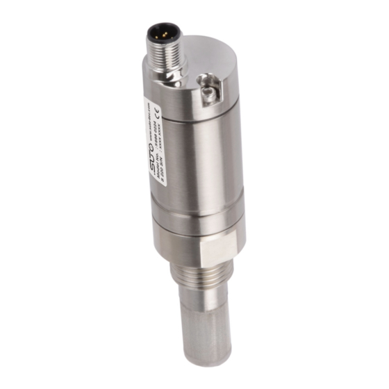
Dew point sensor
Hide thumbs
Also See for S220:
- Instruction and operation manual (25 pages) ,
- Instruction and operation manual (36 pages)
Table of Contents
Advertisement
Quick Links
Advertisement
Table of Contents

Related Manuals for SUTO S220


Summary of Contents for SUTO S220
- Page 1 English Instruction and operation manual S220 Dew point sensor...
- Page 2 The device is destined exclusively for the described application. SUTO offers no guarantee for the suitability for any other purpose. SUTO is also not liable for consequential damage resulting from the delivery, capability or use of this device.
-
Page 3: Table Of Contents
8.1 Analog output ..............13 8.2 Modbus output ..............14 9. Optional extra accessories............15 9.1 Measuring chambers ............15 9.2 Service kit................15 10. Calibration................16 11. Maintenance................16 12. Disposal or waste..............16 13. Warranty................17 Appendix A - Modbus communication example........18 Appendix B - LRC and CRC calculation..........20 S220... -
Page 4: Safety Instructions
• Consider all regulations for electrical installations. • The system must be disconnected from any power supply during maintenance work. • Any electrical work on the system is only allowed by authorized qualified personal. S220... - Page 5 • Make sure that transportation temperature of the sensor is between -30 ... +70°C. • For storage and transportation it is recommended to use the packaging which comes with the sensor. • Please make sure that the storage temperature of the sensor is between -20 ... 50°C. S220...
-
Page 6: Application
• For the storage the humidity has to be <90%, no condensation. 2. Application The S220 is a dew point sensor which is designed to monitor the dew point in industrial application within the permissible operating parameters. These parameters can be found in the technical data section. -
Page 7: Technical Data
Power supply 12 ... 30 VDC / 30 mA 4.3 Output-Signals Analog output 4 ... 20 mA, 3-wire 4 ... 20 mA, 2-wire Analog output scaling 4 mA = -100°C Td 20 mA = +20°C Td Modbus output RS-485 S220... -
Page 8: Accuracy
Temperature: 0.3°C Pressure: 0.05 bar Repeatability ± 0.5°C Stated accuracy at Ambient/process temperature 23°C ± 3°C Process temperature 23°C ± 3°C Ambient/process humidity <95% rH, no condensation Airflow > 2 l/min at the sensor tip Accuracy : Valid working range: S220... -
Page 9: Dimensional Drawing
5. Dimensional drawing 5. Dimensional drawing S220... -
Page 10: Determination Of The Installation Point
• The sensor is for indoor use only! At an outdoor installation, the sensor must be protected from solar radiation and rain. • It is strongly recommend not to install S220 permanently in wet environment as it exists usually right after a compressor outlet. -
Page 11: Installation Procedure
• Install the sensor only if the system is pressureless. • Not less than 1/3 of the sensor tip should be inside of the pipe. For this please check the size of the nozzle. • The inner thread has to be G 1/2”. S220... -
Page 12: Electrical Connection
7.3 Electrical connection Connection pins connector plug M12 Connection pins (view from the clamping side) Pin assignment connector plug M12 Model Pin 1 Pin 2 Pin 3 Pin 4 Pin 5 0220 0221 0222 S220... -
Page 13: Signal Outputs
Model Analog output S699 0220 1 x 4 ... 20 mA, 3-wire (active) S699 0221 2 x 4 ... 20 mA, 3-wire (active) S699 0223 S699 0225 1 x 4 ... 20 mA, 2-wire (passive) S220... -
Page 14: Modbus Output
Inter-frame spacing : 7 char Remarks • Modbus communication settings can be changed by the service software. • To learn more about Modbus communication, see Appendix A - Modbus communication example and Appendix B - LRC and CRC calculation. S220... -
Page 15: Optional Extra Accessories
The diagram below shows the connection when using the optional service kit. Please ensure that also in this case the power supply of either S220 or of the service kit is connected because the USB port cannot supply enough power. -
Page 16: Calibration
The sensor, the accessories and its packings must be disposed according to your local statutory requirements. The dispose can also be carried by the manufacturer of the product, for this please contact the manufacturer. S220... -
Page 17: Warranty
13. Warranty 13. Warranty SUTO provides a warranty for this product of 24 months covering the material and workmanship under the stated operating conditions from the date of delivery. Please report any findings immediately and within the warranty time. If faults occurring during the warranty time SUTO... -
Page 18: Appendix A - Modbus Communication Example
Coil address Hi 1 byte Coil address Hi 1 byte Coil address Lo 1 byte Coil address Lo 1 byte Data Hi 1 byte Data Hi 1 byte Data Lo 1 byte Data L 1 byte 2 bytes 2 bytes S220... - Page 19 1 byte Slave address 1 byte Function code 1 byte Function code 1 byte 2 bytes Byte count 1 byte Slave ID 2 bytes Device run 2 bytes indicator Product code 2 bytes Product name 20 bytes 2 bytes S220...
-
Page 20: Appendix B - Lrc And Crc Calculation
The function takes two arguments: unsigned char *auchMsg; /* A pointer to the message buffer containing binary data */ /* to be used for generating the LRC, unsigned short usDataLen; /* The quantity of bytes in the message buffer. LRC generation function S220... - Page 21 6. Repeat steps 2 through 5 for the next 8-bit byte of the message. Continue doing this until all bytes have been processed. 7. The final content of the CRC register is the CRC value. 8. When the CRC is placed into the message, its upper and lower S220...
- Page 22 0x30, 0x31, 0xF1, 0x33, 0xF3, 0xF2, 0x32, 0x36, 0xF6, 0xF7, 0x37, 0xF5, 0x35, 0x34, 0xF4, 0x3C, 0xFC, 0xFD, 0x3D, 0xFF, 0x3F, 0x3E, 0xFE, 0xFA, 0x3A, 0x3B, 0xFB, 0x39, 0xF9, 0xF8, 0x38, 0x28, 0xE8, 0xE9, 0x29, 0xEB, 0x2B, 0x2A, 0xEA, S220...
- Page 23 /* will index into CRC lookup table */ while(usDataLen—) /* pass through message buffer */ uIndex = uchCRCHi ^ *puchMsg++ ; /* calculate the CRC */ uchCRCHi = uchCRCLo ^ auchCRCHi[uIndex] ; uchCRCLo = auchCRCLo[uIndex] ; return (unsigned short int)((uchCRCHi << 8) | uchCRCLo); S220...
- Page 24 SUTO iTEC GmbH SUTO iTEC (ASIA) Co., Ltd. Werkstr. 2 Room 10, 6/F, Block B, Cambridge Plaza 79426 Buggingen 188 San Wan Road, Sheung Shui, N.T. Germany Hong Kong Tel: +49 (0) 7631 936889-0 Tel: +852 2328 9782 Fax: +49 (0) 7631 936889-19...
Need help?
Do you have a question about the S220 and is the answer not in the manual?
Questions and answers