SUTO S415 Instruction And Operation Manual
Thermal mass flow sensor
Hide thumbs
Also See for S415:
- Instruction and operation manual (24 pages) ,
- Instruction and operation manual (32 pages)
Table of Contents
Advertisement
Quick Links
Advertisement
Table of Contents

Related Manuals for SUTO S415


Summary of Contents for SUTO S415
- Page 1 English Instruction and operation manual S415 Thermal mass flow sensor...
- Page 2 The device is destined exclusively for the described application. SUTO offers no guarantee for the suitability for any other purpose. SUTO is also not liable for consequential damage resulting from the delivery, capability or use of this device.
-
Page 3: Table Of Contents
9.2 Pulse output...............14 9.2.1 Pulse Connection Diagram..........16 9.3 Modbus output..............17 10 Configuration................18 11 Calibration................19 12 Disposal or waste..............19 13 Appendix A - Specifications............20 13.1 Flow ranges..............20 13.2 Error code.................21 13.3 Order table...............21 14 Appendix B - Modbus communication example......22 S415... -
Page 4: Safety Instructions
• Consider all regulations for electrical installations. • The system must be disconnected from any power supply during maintenance. • Any electrical work on system is only allowed by authorized qualified personal. S415... - Page 5 • Do not exceed the maximum operating temperature at the sensors tip. • Avoid condensation on the sensor element as this will affect accuracy enormously. Storage and transportation • Make sure that the transportation temperature is between -30 ... +70°C. S415...
-
Page 6: Registered Trademarks
• Avoid direct UV and solar radiation during storage. • For the storage the humidity must be <90% with no condensation. 2 Registered trademarks SUTO ® Registered trademark of SUTO iTEC MODBUS ® Registered trademark of the Modbus Organization, Hopkinton, USA HART ®... -
Page 7: Rf Exposure Information And Statement
• Connect the equipment into an outlet on a circuit different from that to which the receiver is connected. • Consult the dealer or an experienced radio/TV technician for help • This device and its antenna(s) must not be co-located or operating in conjunction with any other antenna or transmitter. S415... -
Page 8: Application
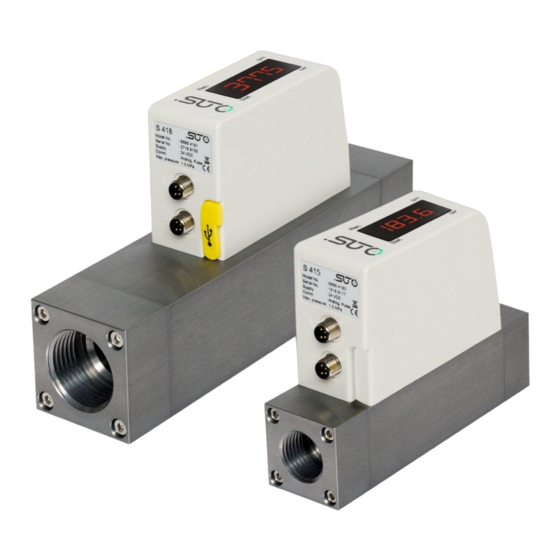
4 Application 4 Application The S415 is the thermal mass flow sensor that is designed to measure the volumetric flow and consumption of compressed air and nitrogen within the permitted operating parameters. (See Technical data on the next page.) The default unit settings are: volumetric flow in l/min and total Consumption in m . -
Page 9: Technical Data
See dimensional drawing on page 11. Display 4-digit LED display Tube diameter DN8, DN15, DN20, DN25, and DN32 Process connection G inner thread ISO 228-1 Weight 0.45 kg (DN8), 0.44 kg (DN15) 0.97 kg (DN20), 0.94 kg (DN25) 1.7 kg (DN32) S415... -
Page 10: Electrical Data
Process pressure at 0.6 MPa Repeatability ± 1% of reading Sampling rate 3 samples per second * The specified accuracy is valid only within the minimum and maximum flow rates that are stated in section 13.1 on page 20. S415... -
Page 11: Dimensional Drawing
7 Dimensional drawing 7 Dimensional drawing A (mm) B (mm) C (mm) D (mm) E (mm) DN8/15 35.0 48.0 120.4 35.0 93.0 DN20/25 48.0 61.0 178.0 48.0 106.0 DN32 60.0 118.0 222.0 60.0 73.0 S415... -
Page 12: Installation
• The sensor is for indoor use only! At an outdoor installation, the sensor must be protected from solar radiation and rain. • It is strongly recommend not to install S415 permanently in wet environment which exists usually right after a compressor outlet. -
Page 13: Electrical Connection
5 m cable with a M8 connector on one side and open wires on the other side. To make the S415 work, one cable connection is sufficient. However, if the pulse output is to be used or the supply and the signal need to be on separate cables, a second connection cable must be ordered. -
Page 14: Sensor Signal Outputs
The sensor outputs one pulse per a consumption unit. This pulse output can be connected to an external pulse counter to count the total consumption. The number of m per second are summed up and indicated after one second. Pulse length depends on flow rate. S415... - Page 15 9 Sensor signal outputs Volumetric Volumetric Pulse length Max. pulse flow flow [ms] output per hour ≦ ≦ 10800 1080 > 3 > 10800 2880 > 6 > 21600 3960 S415...
-
Page 16: Pulse Connection Diagram
9 Sensor signal outputs 9.2.1 Pulse Connection Diagram Variant 1: Variant 2: S415... -
Page 17: Modbus Output
Byte order Byte sequencing (HEX) Example MID-LITTLE-ENDIAN A B C D 0x 0A 11 42 C5 (Read from the device) LITTLE-ENDIAN B A D C 0x 11 0A C5 42 BIG-ENDIAN C D A B 0x 42 C5 0A 11 S415... -
Page 18: Configuration
10 Configuration 10 Configuration To change any settings on the S415, please download and install the service App S4C-FS from the Google Play store or our Website. This App works on any Android system with Bluetooth supported. To be allowed to change settings, the App needs to scan the QR code attached on the side of the sensor head or on the calibration certificate. -
Page 19: Calibration
The sensor, the accessories and its packing must be disposed according to your local statutory requirements. The dispose can also be carried by the manufacturer of the product, for this please contact the manufacturer. S415... -
Page 20: Appendix A - Specifications
0°C and 1013.25 hPa Unit: l/min DN15 DN20 DN25 DN32 Min Max Min Standard 4.44 222 17.8 890 35.6 1780 62.2 3110 5335 range (S) 0.89 44.5 3.56 178 7.12 356 12.4 1067 range (L) S415... -
Page 21: Error Code
Order no. Size Range Output Description S695 415 S415, thermal mass flow meter, 3% o.RDG., 24 VDC DN8 G inner thread DN15 G inner thread DN20 G inner thread DN25 G inner thread DN32 G inner thread Standard range version of S415... -
Page 22: Appendix B - Modbus Communication Example
Coil address Hi 1 byte Coil address Hi 1 byte Coil address Lo 1 byte Coil address Lo 1 byte Data Hi 1 byte Data Hi 1 byte Data Lo 1 byte Data L 1 byte 2 bytes 2 bytes S415... - Page 23 1 byte Slave address 1 byte Function code 1 byte Function code 1 byte 2 bytes Byte count 1 byte Slave ID 2 bytes Device run 2 bytes indicator Product code 2 bytes Product name 20 bytes 2 bytes S415...
- Page 24 SUTO iTEC GmbH SUTO iTEC (ASIA) Co., Ltd. Grißheimer Weg 21 Room 10, 6/F, Block B, Cambridge Plaza D-79423 Heitersheim 188 San Wan Road, Sheung Shui, N.T. Germany Hong Kong Tel: +49 (0) 7634 50488 00 Tel: +852 2328 9782...
Need help?
Do you have a question about the S415 and is the answer not in the manual?
Questions and answers