SUTO S421 Instruction And Operation Manual
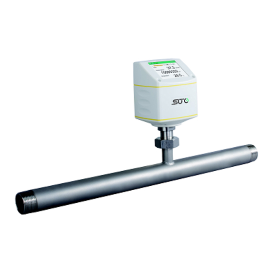
Thermal mass flow sensor
Hide thumbs
Also See for S421:
- Instruction and operation manual (40 pages) ,
- Instruction and operation manual (44 pages) ,
- Instruction and operation manual (48 pages)
Table of Contents
Advertisement
Quick Links
Advertisement
Table of Contents

Related Manuals for SUTO S421


Summary of Contents for SUTO S421
- Page 1 English Instruction and operation manual S421 Thermal mass flow sensor...
- Page 2 The device is designed exclusively for the described application. SUTO offers no guarantee for the suitability for any other purpose. SUTO is also not liable for consequential damage resulting from the delivery, capability or use of this device.
-
Page 3: Table Of Contents
7 Dimensional drawing..............12 8 Installation considerations............15 8.1 Inlet and Outlet sections............15 9 Sensor Installation ..............19 9.1 Installing the S421..............19 9.2 Removing the S421 ............20 9.3 Electrical connection ............21 9.3.1 M12 connection pins............21 9.3.2 Ethernet connection............23 10 Sensor signal outputs...............25 10.1 Analog output..............25 10.2 Pulse output..............25... -
Page 4: Safety Instructions
• Consider all regulations for electrical installations. • The system must be disconnected from any power supply during maintenance. • Any electrical work on system is only allowed by authorized qualified personal. S421... - Page 5 • Always observe the direction of the flow when installing the sensor. The direction is indicated on the housing. • Do not exceed the maximum operation temperature at the sensors tip. • Avoid condensation on the sensor element as this will affect accuracy enormously. S421...
-
Page 6: Registered Trademarks
• Avoid direct UV and solar radiation during storage. • For the storage the humidity must be <90%, no condensation. 2 Registered trademarks SUTO ® Registered trademark of SUTO iTEC MODBUS ® Registered trademark of the Modbus Organization, Hopkinton, USA HART ®... -
Page 7: Rf Exposure Information And Statement
• Consult the dealer or an experienced radio/TV technician for help 。 • This device and its antenna(s) must not be co-located or operating in conjunction with any other antenna or transmitter. S421... -
Page 8: Application
4 Application 4 Application The S421 is tge inline-type flow sensor that is designed to measure the consumption of compressed air and gases within the permissible operating parameters (see chapter 6 Technical Data The S421 can measure the following values: •... -
Page 9: Technical Data
6 Technical Data 6 Technical Data 6.1 General FCC ID: 2ASK2-SUTO-001 Parameters Standard unit flow: Other units: /min, l/min, l/s, cfm, kg/h, kg/min, kg/s Consumption units: , ft , kg Reference conditions ISO1217 20°C 1000 hPa (Standard-Unit) DIN1343 0°C 1013.25 hPa (Norm-Unit) -
Page 10: Electrical Data
Process pressure at 0.6 MPa Repeatability ±0.25% of reading Specified accuracy is valid only within the minimum and maximum flow rates that are indicated in section 6.5. 6.5 Volumetric flow ranges Inch S421 (m³/h) ½" DN15 0.5 ... 90 ¾" DN20 0.9 ... 170 1"... - Page 11 6 Technical Data Inch S421 (m³/h) 2" DN50 4 ... 1000 2½" DN65 6 ... 1500 3" DN80 8 ... 2500 Remarks: • Measuring ranges are stated under following conditions: • Standard flow in air • Reference pressure: 1000 hPa •...
-
Page 12: Dimensional Drawing
1/2”/(DN15) 197.4 186.7 R 1/2” S421-3/4” 3/4”/(DN20) 200.2 186.7 R 3/4” S421-1” 1”/(DN25) 203.6 186.7 R 1” S421-1 1/4” 1 1/4”/ 207.9 186.7 R 1 1/4” (DN32) S421-1 1/2” 1 1/2”/ 210.9 186.7 R 1 1/2” (DN40) S421-2” 2”/(DN50) 216.9 186.7... - Page 13 ØK n x ØL [mm] (mm) (mm) (mm) S421-3/4” 3/4”/ 239.2 186.7 4xØ14 (DN20) S421-1” 1”/(DN25) 244.2 186.7 4xØ14 S421-1 1/4” 1 1/4”/ 256.7 186.7 4xØ18 (DN32) S421-1 1/2” 1 1/2”/ 261.7 186.7 4xØ18 (DN40) S421-2” 2”/(DN50) 269.2 186.7 4xØ18 S421-2 1/2”...
- Page 14 4xØ15.7 (DN15) S421-3/4” 3/4”/ 245.4 186.7 117.3 82.5 4xØ19 (DN20) S421-1” 1”/ 248.7 186.7 123.9 88.9 4xØ19 (DN25) S421-1 1/4” 1 1/4”/ 253.4 186.7 133.3 98.5 4xØ19 (DN32) S421-1 1/2” 1 1/2”/ 264.4 186.7 155.4 114.3 4xØ22.3 (DN40) S421-2” 2”/ 269.3...
-
Page 15: Installation Considerations
• The sensor is for indoor use only! At an outdoor installation, the sensor must be protected from solar radiation and rain. • It is strongly recommend not to install S421 permanently in wet environment, which exists usually right after a compressor outlet. - Page 16 8 Installation considerations The S421 sensor comes with its own measuring section and a straight inlet section, nevertheless additional straight inlet sections must be added to measuring sections to fulfill the minimum inlet requirements. Please refer to the installation types below and select your additional inlet section 'LA' from the table.
- Page 17 DN40 DN50 DN65 DN80 LA (mm) 1100 1500 1700 5. 3 dimensional Bend Section size DN15 DN20 DN25 DN32 DN40 DN50 DN65 DN80 LA (mm) 1200 1400 1800 2500 3000 6. T-piece Section size DN15 DN20 DN25 DN32 DN40 DN50 DN65 DN80 S421...
- Page 18 DN20 DN25 DN32 DN40 DN50 DN65 DN80 LA (mm) 1100 1500 1800 2400 3200 3800 8. Filter or similar (unknown objects) Section size DN15 DN20 DN25 DN32 DN40 DN50 DN65 DN80 LA (mm) 1100 1500 1800 2400 3200 3800 S421...
-
Page 19: Sensor Installation
A1341 ... A1348 (Flange, ANSI 16.5) 9.1 Installing the S421 The S421 is always shipped with mounted measurement section. Please make sure that the sensor is installed correctly to the flow direction in the tube. For this observe the flow direction indicated on the housing, it must match the flow direction of the compressed air or gas. -
Page 20: Removing The S421
9 Sensor Installation 9.2 Removing the S421 The following steps explain the procedure of an appropriate removal of the sensor. ATTENTION! Only remove the sensor if the system is in a pressureless condition. 1. Hold the flow sensor. 2. Release the connection nut at the connection thread. -
Page 21: Electrical Connection
(View onto the sensor connector) Connector types: A = M12 5-pin B = M12 5-pin For the following output options: Output type A1424 Modbus/TCP Connector types: A = M12 5-pin B = M12 8-pin X-coded Ethernet connection pins, male S421... - Page 22 Negative supply voltage +VB: Positive supply voltage Positive 4 ... 20 mA signal Negative 4 ... 20 mA signal Pulse output Isolated pulse output Flow direction input Modbus/RTU data + Modbus/RTU data - M-Bus: M-Bus data N/A: Not applicable S421...
-
Page 23: Ethernet Connection
When Modbus/TCP is chosen as the sensor output, a 5 m 8-pore cable is supplied in the delivery package, which has the M12 and RJ45 plugs on both ends. RJ45 is used to connect the device to a PoE switch. Front view of the M12 plug, female S421... - Page 24 Orange (O) Rx+ / -Vb / +Vb White-Green (W-G) Pair 3 Rx- / -Vb / +Vb Green (G) NA / -Vb White-Brown (W-BR) Pair 4 NA / -Vb Brown (BR) NA/ +Vb White-Blue (W-BL) Pair 1 NA/ +Vb Blue (BL) S421...
-
Page 25: Sensor Signal Outputs
0 to max flow. The corresponding flow rates in different pipe sizes can be calculated using the free "Flow range calculator" tool available in http://www.suto-itec.com. For more information, see section 6.5. For other ranges, please contact the manufacturer. 10.2 Pulse output The sensor outputs one pulse per a consumption unit. - Page 26 10 Sensor signal outputs If the flow rate is too high, the S421 cannot output the pulses with default settings (one pulse per consumption unit). In this case, the pulse can be set to 1 pulse per 10 consumption units or 1 pulse per 100 consumption units, using the Android service App (S4C-FS) or a connected display .
-
Page 27: Pulse Connection Diagrams (A1410)
10 Sensor signal outputs 10.2.1 Pulse Connection Diagrams (A1410) Using the isolated pulse switch (Connector B Pin 2 and 3) Variant 1: Variant 2: S421... -
Page 28: Pulse Connection Diagrams (A1413)
10 Sensor signal outputs 10.2.2 Pulse Connection Diagrams (A1413) Using the isolated pulse switch (Connector B Pin 4 and 5) Variant 1: Variant 2: S421... - Page 29 10 Sensor signal outputs Using the Pulse Output P+ (Connector A Pin 5) Variant 1: Variant 2: *GND of the external pulse counter may be connected to -V of the sensor. S421...
-
Page 30: Modbus Output
Holding register table (Modbus/RTU and Modbus/TCP) Modbus Channel description Resolution Format Length register address Flow FLOAT 4-Byte Consumption UNIT32 4-Byte Reverse flow* FLOAT 4-Byte * Value 0 identifies the same direction and 1 identifies the reverse direction. S421... - Page 31 Data bytes Total consumption 4-byte Flow 4-byte M-Bus status 4-byte Communication parameters: Primary Address Secondary Address 8-digit serial number of the sensor Manufacturer Code 0x15C4 M-Bus version Baud rate 2400 Response delay (ms) Response timeout (ms) : Receive timeout (ms) S421...
-
Page 32: Sensor Display (Optional)
Finally, the display enters the standard mode, showing the online values as shown below. Home page • Status bar • Moving bar to indicate flow value • Measurement values S421... -
Page 33: Configuration Using The Display
4. Use the “Up” and “Down” keys to select a desired entry box or adjust the values. 5. Press the “Enter” key to confirm the changes. S421... -
Page 34: Service App S4C-Fs
This ensures that only authorized users can access the sensor settings. For more information about instructions on S4C-FS, see the S4C-FS Instruction and Operation Manual, which is available on the SUTO iTEC Website. ATTENTION! -
Page 35: Calibration
16 Appendix A Modbus communication example 03 (0x03) Read holding register Request Response Slave address 1 byte Slave address 1 byte Function code 1 byte Function code 1 byte Starting address 1 byte Byte count 1 byte S421... -
Page 36: Appendix A Modbus Communication Example
Coil address Hi 1 byte Coil address Hi 1 byte Coil address Lo 1 byte Coil address Lo 1 byte Data Hi 1 byte Data Hi 1 byte Data Lo 1 byte Data L 1 byte 2 bytes 2 bytes S421... - Page 37 1 byte Slave address 1 byte Function code 1 byte Function code 1 byte 2 bytes Byte count 1 byte Slave ID 2 bytes Device run 2 bytes indicator Product code 2 bytes Product name 20 bytes 2 bytes S421...
- Page 38 S421...
- Page 39 S421...
- Page 40 SUTO iTEC GmbH SUTO iTEC (ASIA) Co., Ltd. Grißheimer Weg 21 Room 10, 6/F, Block B, Cambridge Plaza D-79423 Heitersheim 188 San Wan Road, Sheung Shui, N.T. Germany Hong Kong Tel: +49 (0) 7634 50488 00 Tel: +852 2328 9782...
Need help?
Do you have a question about the S421 and is the answer not in the manual?
Questions and answers