Table of Contents
Advertisement
Quick Links
Advertisement
Table of Contents

Related Manuals for SUTO S201


Summary of Contents for SUTO S201
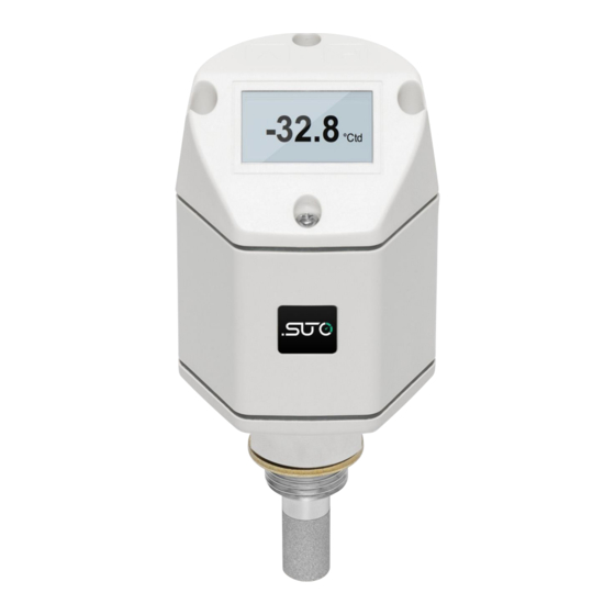
- Page 1 English Instruction and operation manual S201 Dew point sensor...
- Page 2 The device is destined exclusively for the described application. SUTO offers no guarantee for the suitability for any other purpose. SUTO is also not liable for consequential damage resulting from the delivery, capability or use of this device.
-
Page 3: Table Of Contents
9.2 Relay output ..............15 10 Sensor display ................15 10.1 Starting process..............16 10.2 Error messages..............16 10.3 Configuration using the display..........17 11 Optional extra accessories............18 11.1 Measuring chambers ............18 11.2 Service kit................18 12 Calibration................19 13 Maintenance................19 14 Disposal or waste..............19 15 Warranty................20 S201... - Page 4 • Consider all regulations for electrical installations. • The system must be disconnected from any power supply during maintenance work. • Any electrical work on the system is only allowed by authorized qualified personal. S201...
- Page 5 • Please make sure that the storage temperature of the sensor is between -10 ... +50°C. • Avoid direct UV and solar radiation during storage. • For the storage the humidity must be <95% rH, no condensation. S201...
-
Page 6: Registered Trademarks
Registered trademark of the PROFIBUS User Organization, Karlsruhe, Germany 3 Application The S201 is a dew point sensor which is designed to monitor the dew point in industrial application within the permissible operating parameters. These parameters can be found in the technical data section. -
Page 7: Features
• Very fast response time ensures safe and reliable indication whenever dew points are out of valid ranges. • Can be installed directly into dryers through G ½” thread. • High accuracy of ± 2°C Td dew point. S201... -
Page 8: Technical Data
UNF 5/8” thread (on request) Weight 226 g 5.2 Electrical data Power supply 12 ... 30 VDC / 100 mA 5.3 Output-signals Analog output Signal: 4 ... 20 mA, 3 wire Analog output scaling 4 mA = -60°C Td S201... - Page 9 Technical data 20 mA = +20°C Td Relay output NO, 32 VDC, 500 mA Accuracy: Valid working range: S201...
-
Page 10: Dimensional Drawing
Dimensional drawing 6 Dimensional drawing S201... -
Page 11: Determination Of The Installation Point
• The sensor is for indoor use only! At an outdoor installation, the sensor must be protected from solar radiation and rain. • It is strongly recommend not to install S201 permanently in wet environment as it exists usually right after a compressor outlet. -
Page 12: Installation Procedure
Not less than 1/3 of the • sensor tip should be inside of the pipe. For this please check the size of the nozzle. The inner thread must be • G 1/2”. S201... -
Page 13: Electrical Connection
8.3 Electrical connection The dew point sensor is equipped with tow Connector plugs “A” and “B”. The cables are connected to the sensor through the M12 connector. Connector plug A Connector plug B S201... - Page 14 Negative supply voltage Positive supply voltage Positive 4 ... 20 mA signal N/A Not available NO1 Relay output NO2 Relay output SEL Internal signal ATTENTION! Do not screw the M12 plug using force. Otherwise, it may damage the connecting pins. S201...
-
Page 15: Signal Outputs
9.2 Relay output The S201 has an relay alarm output. It is possible to monitor e.g. the dew point value and gives an alarm at a particular threshold value. -
Page 16: Starting Process
If the problems still exists please contact a technician of the manufacturer. If the sensor and the display settings are not matching, the instrument will Error: show this message. Please contact a Sensor unmatch! technician of the manufacturer. S201... -
Page 17: Configuration Using The Display
Sensor display 10.3 Configuration using the display The S201 is usually configured ex factory according to the ordered customer settings. In case of settings must be changed, please observe the following steps. 1. At first keep the Enter key ( ... -
Page 18: Optional Extra Accessories
The diagram below shows the connection when using the optional service kit. Please ensure that also in this case the power supply of either S201 or of the service kit is connected because the USB port is not supplying enough power. -
Page 19: Calibration
The sensor, the accessories and its packings must be disposed according to your local statutory requirements. The dispose can also be carried by the manufacturer of the product, for this please contact the manufacturer. S201... -
Page 20: Warranty
Warranty 15 Warranty SUTO provides a warranty for this product of 24 months covering the material and workmanship under the stated operating conditions from the date of delivery. Please report any findings immediately and within the warranty time. If faults occur during the warranty time, SUTO will... - Page 21 S201...
- Page 22 S201...
- Page 23 S201...
- Page 24 SUTO iTEC GmbH SUTO iTEC (ASIA) Co., Limited Werkstr. 2 Room 10, 6/F, Block B, Cambridge Plaza 79426 Buggingen 188 San Wan Road, Sheung Shui, N.T. Germany Hong Kong Tel: +49 (0) 7631 936889-0 Tel: +852 2328 9782 Fax: +49 (0) 7631 936889-19...
Need help?
Do you have a question about the S201 and is the answer not in the manual?
Questions and answers