Page 1
English Instruction and operation manual S401 
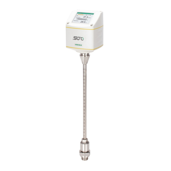
Thermal mass flow sensor...
Page 2
The device is destined exclusively for the described application. SUTO offers no guarantee for the suitability for any other purpose. SUTO is also not liable for consequential damage resulting from the delivery, capability or use of this device.
1 Safety instructions 1 Safety instructions Please check if this instruction manual matches with the product type. Please observe all notes and instructions indicated in this manual. It contains essential information which must be observed before and during installation, operation and maintenance.
Page 5
1 Safety instructions ATTENTION! Permitted operating parameters! Observe the permitted operating parameters, any operation exceeding this parameters can lead to malfunctions and may lead to damage on the instrument or the system. • Do not exceed the permitted operating parameters. •...
• Avoid direct UV and solar radiation during storage. • For the storage the humidity must be <90%, no condensation. 2 Registered trademarks SUTO ® Registered trademark of SUTO iTEC MODBUS ® Registered trademark of the Modbus Organization, Hopkinton, USA HART ®...
3 RF exposure information and statement 3 RF exposure information and statement This equipment complies with FCC RF radiation exposure limits set forth for an uncontrolled environment. This equipment should be installed and operated with minimum distance of 20 cm between the radiator and your body.
4 Application 4 Application The S401 is a flow sensor that is designed to measure the consumption of compressed air and gases within the permissible operating parameters (See chapter 6 Technical data The S401 can measure the following values: • Volumetric flow of the compressed air or gas (default unit: m /h).
6 Technical data Tube diameter 1/2” to 12” (bigger diameters available on request) Process connection G1/2” (ISO 228/1) Weight 0.9 kg (220 mm standard) 0.85 kg (160 mm), 0.95 kg (300 mm), 1.0 kg (400 mm) 6.2 Electrical data Power supply 15 ...
• To calculate flow ranges based on pipe and reference conditions in your site, download and install the "Flow range calculator" tool for free from http://www.suto-itec.com. • To fast access the tool download page, enter "flowrange" (without spaces) in the search field and click the search result.
8 Determining the installation point 8 Determining the installation point In order to maintain the accuracy stated in the technical data, the sensor must be insert in the center of a straight pipe section with unhindered flow characteristics. Unhindered flow characteristics are achieved if the section in front of the sensor (inlet) and behind the sensor (outlet) are sufficiently long, absolutely straight and free of obstructions such as edges, seams, curves etc..
8.1 Reserving inlet and outlet sections Because the thermal measuring principle may be sensible to inlet and outlet conditions, we recommend the following minimum straight inlet and outlet sections be reserved to ensure an accurate measurement. The S401 sensors should be always installed upstream from obstacles like valves, filter, reductions etc.
Page 15
• 3 dimensional Bend • T-piece • Shut-off valve • Filter or similar (unknown objects) S401...
9 Sensor installation 9 Sensor installation Before installing the sensor, please make sure that all components listed below are included in your package. Qty Description Item no. Sensor S695 4100 S695 4101 S695 4102 S695 4103 Sealing ring Alignment key Depending on orders: Plug: C219 0059 M12 plug or M12 cable...
9 Sensor installation 9.2 Installation procedure The following steps explain the procedure of an appropriate installation. 9.2.1 Calculating the installation depth Center installation is the default and recommended installation method. The sensor tip must be placed in the center of the pipe. The meter shaft has a scale engraved.
Page 18
9 Sensor installation For bigger pipe diameters (>200 mm), the sensor can be installed with only a 100 mm insertion depth as the alternative. This allows one sensor to be used for all pipe sizes. Remark: To enable the 100 mm installation method, use the S4C-FS app or the service software.
9 Sensor installation 9.2.2 Installing the sensor First please observe the flow direction indicated on the housing or on the shaft. It must match the flow direction of the compressed air or gas. 1. Close the ball valve. 2. Make sure that he probe tip is completely covered by the connection head (see the photo on the left).
9 Sensor installation 9. Double check the installation depth because the shaft might be pushed away from its original position by the compressed gas. 10. Tighten the locking nut with clamping torque 20 … 30 Nm. 9.2.3 Removing the sensor 1.
9 Sensor installation 9.3.1 M12 connection pins For the following output versions: Output type A1410 4 ... 20 mA + Pulse Modbus/RTU A1411 A1412 M-Bus A1413 4 ... 20 mA + Pulse compatible to S400 General connection pins, male (View onto the sensor connector) Connector types: A = M12 5-pin / B = M12 5-pin For the following output versions:...
Page 22
9 Sensor installation M12 pin assignment Output Type Connector Pin 1 Pin 2 Pin 3 Pin 4 Pin 5 4 ... 20 mA plus pulse (P/N: A1410) Modbus/RTU (P/N: A1411) M-Bus (P/N: A1412) +VB M-Bus M-Bus 4 ... 20 mA plus pulse, compatible to S400 (P/N: A1413) Modbus/TCP...
9 Sensor installation 9.3.2 Ethernet connection The device can be powered by the following ways: • Using the connector A • Using the PoE (Power over Ethernet) function, which is integrated into the Ethernet connection on connector B. To power the unit via PoE, a switch that supports PoE is needed. PoE comes into two standards: •...
Page 24
9 Sensor installation Connection cable – M12 X-coded to RJ45 When Modbus/TCP is chosen as the sensor output, a 5 m 8-pore cable is supplied in the delivery package, which has the M12 and RJ45 plugs on both ends. RJ45 is used to connect the device to a PoE switch. Front view of the M12 plug, female The 8-position pin/pair assignment on the RJ45 side must comply with the T568B wiring method.
The corresponding flow rates in different pipe sizes can be calculated using the free "Flow range calculator" tool available in http://www.suto- itec.com. For more information, see section 6.5. 10.2 Pulse output The sensor outputs one pulse per a consumption unit. This pulse output can be connected to an external pulse counter to count the total consumption.
Page 26
10 Sensor signal outputs In case the flow rate is too high the S401 can not output the pulses with default settings (one pulse per consumption unit). For this the pulse can be set by our service software or a connected display to 1 pulse per 10 consumption units or 1 pulse per 100 consumption units.
10 Sensor signal outputs 10.2.1 Pulse connection diagrams (A1410) Using the isolated pulse switch (Connector B Pin 2 and 3) Variant 1: Variant 2: 10.2.2 Pulse connection diagrams (A1413) Using the isolated pulse switch (Connector B Pin 4and 5) Variant 1: S401...
Page 28
10 Sensor signal outputs Variant 2: Using the pulse output P+ (Connector A Pin 5) Variant 1: Variant 2: *GND of the external pulse counter may be connected to -V of the sensor. S401...
10 Sensor signal outputs 10.3 Modbus output Mode : RTU Baud rate : 19200 Last digits of serial Device address number Framing / : 8, N, 1 parity / stop bit Response time : 1 second Response delay : 0 ms Inter-frame : 7 char spacing...
10 Sensor signal outputs In the response message that the device returns to the master: • Function code: 03 • Byte order (32-bit data): MID-LITTLE-ENDIAN. Remarks: To properly decode the 4-byte float and unsigned integer data in the response message, the master must change the byte order from MID-LITTLE-ENDIAN to the order that it is using (LITTLE-ENDIAN or BIG-ENDIAN).
11 Sensor display (optional) 11 Sensor display (optional) The Sensor display enables you to: • View the online flow and consumption values • View error messages • Change the sensor settings. Enter key” = “ Up key” “ Down key” = “...
11 Sensor display (optional) 11.1 Starting process After powered up, the display starts automatically with an initialisation procedure. During the next eight seconds the display will show the current software version and build the connection to the sensor. Now the display goes to the standard mode, showing the online values.
11 Sensor display (optional) 11.2 Configuration using the display The following settings can be changed via display or service software. • Pipe diameter – for flow calculation. • Gas type – select the gas to be measured. • Flow unit – select unit for flow value. Steps for checking and changing settings are described as follows: 1.
S4C-FS is an Android-based app that enables you to view online measurements and change settings for SUTO flow meters remotely. You can download S4C-FS from the Google Play Store or SUTO website. To change settings, you must scan the QR code attached on the side of the sensor head or on the calibration certificate.
13 Calibration 13 Calibration The sensor is calibrated ex work. The exact calibration date is printed on the certificate which is supplied together with the sensor. The accuracy of the sensor is regulated by the onsite conditions, and parameters like oil, high humidity or other impurities can affect the calibration and furthermore the accuracy.
Need help?
Do you have a question about the S401-S and is the answer not in the manual?
Questions and answers