
Related Manuals for Kverneland 610


Summary of Contents for Kverneland 610
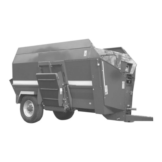
- Page 1 608, 610, 612, 614, 616 & 618 Operator’s Manual Date of publication 08/2008 Date printed 08/2008 Language Application as from machine No. KVT6001208 Reference No. KD1561049...
-
Page 2: Table Of Contents
Policy Statement/Machine Details ......................1 Specifications/Optional Equipment and Accessories ................3 SAFETY FIRST - General ......................... 5 SAFETY FIRST - Kverneland 608, 610, 612, 614, 616 and 618 .............. 6 Lubrication Chart ............................7 Section 1 - Attaching Machine to Tractor ....................8 Section 2 - Operating the Machine ...................... - Page 3 Delivery Date Please complete the above details for easy reference. Kverneland pursues a policy of constant development of its products and reserves the right to improve or alter its products without any obligation to modify or replace machines previously sold.
-
Page 4: Specifications/Optional Equipment And Accessories
SPECIFICATIONS Conveyor dimensions based on the Kverneland 600 series fitted with 315/80 x 15.3 wheels... - Page 5 SPECIFICATIONS Capacity 10.5 Maximum payload (mix load weight): Standard hitch: Kg 3500 4400 5200 6100 7200 8000 'German' hitch: Kg 2500 3100 3500 4100 5600 6200 Unladen weight: Kg 3500 3600 4600 4700 5300 5400 Overall height ‘C’ – 12.50/80 x 15.3 2.42 m 2.69 m wheels...
-
Page 6: Safety First - General
Check the machine regularly for loose or damaged parts. Pay particular attention to the condition of ALL safety guards. Always use genuine Kverneland replacement parts in the interest of SAFETY. Failures caused by the use of unofficial replacement parts will NOT be covered by our warranty, nor will any liability be accepted for damages or injury thus incurred. -
Page 7: Safety First - Kverneland 608, 610, 612, 614, 616 And 618
NO LIABILITY WILL BE ACCEPTED where using the machine in any manner other than that detailed in this manual causes injury or damage. LUBRICANTS: Kverneland will not be held responsible for failure caused by the use of incorrect lubricants (see Sections 4 and 6) . -
Page 8: Lubrication Chart
Total 0.6 litres Shell Calithia EPT2 industrial multi-purpose grease and Shell Super Universal Farm Oil are recommended by Kverneland for the above applications. Where other lubricants are used, they must meet the specifications of the Shell products. IMPORTANT! The oil bath must be filled with 20 litres of universal farm oil or equivalent to a depth of 4 cm... -
Page 9: Section 1 - Attaching Machine To Tractor
Figure 1 The tractor PTO shaft must be 6-spline set to run at 540 r.p.m. Kverneland 600 series diet feeders require as standard a double acting hydraulic service and if a weighing system is specified, a 12 Volt d.c. electrical supply. - Page 10 SETTING THE DRAWBAR HEIGHT ON THE MACHINE 1. PROCEDURE Carry out the following procedure with the machine on firm level ground and with the parking brake applied (where fitted). For machines without a parking brake ensure that the chocks (available as an accessory) are fitted to the wheels. NOTE! The following procedure MUST be carried out whenever attaching the machine to a tractor for the first time and also checked if the tractor is changed.
- Page 11 When the machine is disconnected from the tractor, the hoses should be safely stowed by placing their quick release connectors into the slots provided on the front panel. The Kverneland 600 series is supplied with either 3, 4 or 5 bank cable or electric remote control. CLOSED CENTRE HYDRAULIC SYSTEMS The Kverneland 600 series diet feeders are supplied for use with tractors equipped with open centre hydraulics.
- Page 12 CABLE CONTROLS 1. The control levers for the valve block are mounted on a detachable bracket that can be located inside the tractor cab (Figure 3) The base bracket must be securely fixed to a suitable fixing point on the tractor, the tractor manufactures manual should be consulted to find the most appropriate area.
- Page 13 2. 5 BANK control levers operate the following machine functions: in the direction shown on the control panel (Figure 5) Figure 5 OPENING AND CLOSING THE DISCHARGE DOOR RIGHT Lever 1 3 position lever - open - stop - close. Lever 2 OPENING AND CLOSING THE DISCHARGE DOOR LEFT 3 position lever - open - stop - close.
- Page 14 5 BANK control levers in conjunction with dual discharge conveyors. Figure 5a Discharge door positions are as viewed from the tractor seat Lever 1 < OPENING AND CLOSING DISCHARGE DOOR 3 position lever – pull to open – centre to stop – push to close. Lever 2 >...
- Page 15 REMOTE ELECTRIC HYDRAULIC CONTROLS – TYPE A Figure 6 No 1 EMERGENCY STOP SWITCH In case of need press the red button to stop the machine. Twist anti-clockwise to reset. RED OPERATING LIGHT No 2 On = control panel operating Off = control panel not operating.
- Page 16 REMOTE ELECTRIC HYDRAULIC CONTROLS – TYPE B No 1 < RAISING AND LOWERING CONVEYOR BELT For safety reasons and so that the machine works efficiently the switch must be brought back to the stop position before starting another operation. No 2 <...
- Page 17 ELECTRIC FLOW REGULATION VALVE The flow regulation valve (Figure 7 ) is available with electric controls. It can be controlled by the knob on the control panel and it regulates the discharge conveyor speed. MANUAL FLOW REGULATION VALVE for the adjustment of the discharge belt speed (figure 8). 1.
- Page 18 HYDRAULIC PARKING JACK (WHERE FITTED) The hydraulic parking jack is available as an accessory for Kverneland 600 series machines. The jack raises the drawbar to the required height for hitching to a tractor and can also be used as a parking stand when uncoupling the machine (figure 9).
- Page 19 ELECTRONIC WEIGHING SYSTEM (WHERE FITTED) The electronic weighing system display unit is mounted on a swinging arm at the front of machine and can be positioned to suit operator requirements. For the unit to operate plug the power cable 7-pin connector into the tractor 12-Volt d.c lighting socket.
- Page 20 CONNECTING THE PTO SHAFT Separate the two halves of the PTO shaft and remove the plastic guards from both sections (Figure 12). Release and remove retaining ring catches (1) with a screwdriver. Withdraw cone (2) down length of plastic guard tube (3) and remove. Slide plastic guard tube from shaft; prise open retaining ring and remove from yoke.
- Page 21 For subsequent installations, simply connect the PTO shaft between the tractor and the machine, and connect the safety chains to prevent the guards from rotating. NOTE! Disengage PTO shaft when turning. Before operating the machine, check that the PTO shaft does not: Foul the tractor PTO guard when the machine is turned Foul the tractor three-point linkage when machine is turned.
-
Page 22: Section 2 - Operating The Machine
SECTION 2 - OPERATION SAFETY FIRST! Before loading and operating the machine, ensure that all operator’s have read and thoroughly understood the safety procedures as stated on pages 6 and 7 of this manual. LOADING THE MACHINE SAFETY FIRST! All ingredients MUST be loaded mechanically. NEVER attempt to load the machine by hand except via the mesh covered rear aperture. - Page 23 IMPORTANT! Load to only approximately 85-90% of load volume so as to allow room for the ingredients to mix thoroughly. DO NOT exceed the maximum payload capacity of the machine (see page 5) OVERLOADING the mixing chamber can lead to a notable increase in power consumption and mixing time. If the machine becomes blocked counter rotation of the augers will relieve the pressure.
- Page 24 SAFETY FIRST! NEVER stand on the loading mesh at the rear of machine. The Kverneland 600 series machines can be fitted with a discharge chute instead of the hydraulically driven conveyor mechanism. The chute is designed for discharging feed directly onto the floor or into low sided troughs, but is not suitable for discharging into mangers or raised troughs.
-
Page 25: Section 3 - Machine Settings And Adjustments
SECTION 3 - MACHINE SETTINGS & ADJUSTMENTS OVERLOAD PROTECTION The Kverneland 600 series transmission is protected by a P.T.O shaft shear bolt flange. Use only shear bolt size: M8 x 60 grade 8,8 unplated. NOTE! Always fully investigate the reason for any shearbolt failure. - Page 26 DISCHARGE CONVEYOR BELT - REMOVAL OF BELT AND BELT TENSION (Figure 21) 1. Turn off the tractor engine, remove the keys and put them in your pocket. 2. Remove motor M, by unscrewing screws B. BE CAREFUL not to lose the key on the drive shaft. 3.
- Page 27 TRANSMISSION DRIVE CHAIN ADJUSTMENTS Use a 6mm ‘Allen Key’ open the left & right hand front transmission panels to gain access to the transmission. PRIMARY DRIVE CHAIN ADJUSTMENT 1. The primary drive chain is located behind the front transmission panels. 2.
- Page 28 AUGER TIMING If for maintenance reasons the main drive chain has been disconnected, then the auger timing will require checking as shown in the diagram below (figure 26). If necessary rotate one of the augers to reset the timing and refit the main drive chain. Figure 26 AUGER BLADES BLADES ARE EXTREMELY SHARP.
- Page 29 SHEARBAR CONFIGURATIONS • Standard serrated shearbar set - factory fitted 'standard' configuration - 7 hole inclined shearbar and minimal low level shearbar kit • 7 hole inclined shearbar in - prevents round bales from swamping the augers, reduces power requirement and reduces auger aggression •...
- Page 30 • Optional U-section shearbar set - special order option for fibrous products like ammonia treated 608 & 610 KD1560779 4 hole < Front KD1560783 KD1560784 KD1560779 3 hole 4 hole U-Section Shearbar Layouts 1 With Inclined Shear Bar Fitted Standard...
-
Page 31: Section 4 - Fault Finding
Feed material left in mixing chamber overnight Engage PTO at minimum revs. becoming compacted and harder to mix. Shearbolts installed incorrectly or incorrect type Use original Kverneland spare parts. used. PTO shaft shearbolt flange, worn holes Use original Kverneland spare parts. - Page 32 TRACTOR HYDRAULICS SYMPTOM REMEDY (a) Hydraulic fluid overheating or cavitating. Ensure hydraulic circuit is correctly set for CLOSED CENTRE hydraulics. (b) Tractor spool valve overload. Ensure hydraulic circuit is correctly set for OPEN CENTRE hydraulics. ELECTRONIC DISPLAY UNIT Please refer to the weighing system instruction manual supplied with the machine. NOTE! If the machine is left for a long period of time (e.g.
-
Page 33: Section 5 - Routine Maintenance
SAFETY FIRST! Kverneland recommend that major maintenance or repair work, other than detailed in Sections 4 and 5, are carried out by your Kverneland dealer. No liability will be accepted for any mechanical failure or personal injury sustained as a result of work carried out by unauthorised personnel. - Page 34 WEEKLY 1. Check machine for worn, damage or missing parts. Replace with genuine Kverneland Parts. 2. Check parking brake effectiveness (where fitted). Adjust if necessary. 3. Check that wheel nuts are tightened to the correct torque: Kverneland 608 / 610, 70 mm square axle - 300 Nm.
-
Page 35: Section 6 - Spare Parts
SECTION 6 - SPARE PARTS Spare parts for Kverneland 600 series machines can be obtained from your Kverneland dealer. For a detailed list of available parts, refer to the Parts Book held by your dealer. When ordering spare parts, please give the following information: Name and Serial Number of machine. -
Page 36: Section 7 - Annual Maintenance And Storage
SECTION 7 - ANNUAL MAINTENANCE AND STORAGE At the end of the season’s use and prior to storing the machine, proceed as follows: SAFETY FIRST! Tractor handbrake must be applied, machine brakes applied (or wheels chocked), tractor engine must be switched off and key removed. The PTO shaft MUST be removed before attempting this operation. -
Page 37: Section 9 - Eu Conformity Declaration
98/37/EC Denmark declare under our sole responsibility that the product Kverneland 608 - 618 and accessories to which this declaration relates conforms to the relevant basic safety and health requirements of EU Directive 98/37/EC. For the relevant implementation of the safety and health...
Need help?
Do you have a question about the 610 and is the answer not in the manual?
Questions and answers