
Related Manuals for Kverneland Focus 2


Summary of Contents for Kverneland Focus 2
- Page 1 Focus 2 for sowing machines O p e r a t i n g m a n u a l Edition 6/2007 Printing 10.2007 Language For software from 1.03 For hardware version from – Article number AC 758971...
- Page 2 Copyright and exploitation rights for this document belong to Kverneland Soest GmbH, Germany. Copies, transfer into other media, translations or the use of excerpts or parts are forbidden without express permission from Kverneland. All rights reserved. The contents of this operating man-...
-
Page 3: Table Of Contents
An overview of the device Technical data functions Delivery and assembly/installation....11 Checking the scope of delivery Assembly Connecting up the machine ......12 Safety Connecting the Focus 2 Operation............13 Switching on Opening screen Information screen Storage ............35 Removal Storage Removing faults.......... -
Page 4: To Begin With
To begin with To begin with This operating manual is designed for use by trained agriculturists and T a r g e t g r o u p f o r t h i s persons who are otherwise qualified to work in agriculture and who ha- o p e r a t i n g m a n u a l ve been instructed on how to use this machine. -
Page 5: Safety
Safety Checking the cables Safety Check cables before connecting them up and replace damaged ca- bles. Damaged cables can lead to damage occurring to the machine or to uncontrolled behaviour of the electronic control system. Observe the prescribed temperature range The device will only operate reliably within the prescribed temperature range. -
Page 6: Becoming Familiar With The Machine
The description here applies only to the device specified on the title page. The Focus 2 terminal does not comply with the ISOBUS standard. It can only be used in conjunction with machines made by the Kverne-... -
Page 7: Features
Becoming familiar with the machine Control and monitoring are possible using a terminal in connection wi- F e a t u r e s th further components on the respective machine which can be mat- ched to the type of machine being used. The overall system consists of the components •... -
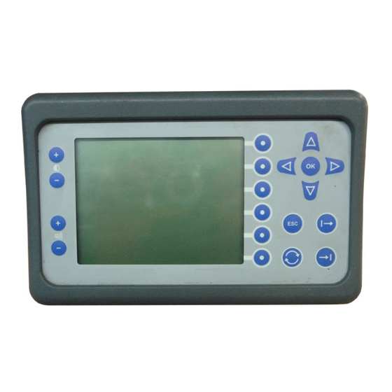
Page 8: An Overview Of The Device
Becoming familiar with the machine A n o v e r v i e w o f t h e d e v i c e The overview shows the display and all of keys which have each been T h e f r o n t s i d e allocated a function. - Page 9 Becoming familiar with the machine The overview shows all connections on the rear side. T h e r e a r s i d e Base for the bracket for fixing devices Connection for the con- trol cable from the job computer ON-OFF switch...
-
Page 10: Technical Data
Becoming familiar with the machine T e c h n i c a l d a t a Focus 2 Power supply (V) DC 12-14 Safety fuse (A) • Switched power cable 1x 30 A; 1x 5 A • Central printed circuit board •... -
Page 11: Delivery And Assembly/Installation
Delivery and assembly/installation Delivery and assembly/installation The following items are mounted on the seed sowing machine at the C h e c k i n g t h e works: s c o p e o f d e l i v e r y •... -
Page 12: Connecting Up The Machine
Connecting up the machine Prerequisites for connecting up the machine are: Connecting up the machine • The machine is coupled to the tractor. • All components are installed in an orderly manner. • All cables and plugs are in perfect condition. Checking the cables S a f e t y Check cables before connecting them up and replace damaged ca-... -
Page 13: Operation
Operation Operation The system is ready to operate after being connected up and can be S w i t c h i n g o n switched on. > Actuate the On-Off switch on the rear side of the terminal The system performs a short self-test. - Page 14 Operation In the top area you can make several settings to adapt the terminal to B a s i c s e t t i n g s a t t h e t e r m i - suit your wishes. These include: n a l >...
- Page 15 Operation Page 2 Separator for numbers (comma or point) Formatting the date Formatting the time of day Metric Imp. Indicating units according to the American system Indicating units according to the British system Indicating units according to the metric system Back to the opening screen To the previous page...
- Page 16 Operation This screen shows the software version. Knowledge of which version D i s p l a y o f t e r m i n a l d a t a of software is being used could be required when calling the technical customer service.
-
Page 17: Information Screen
Operation The information screen displays all of the most important values du- I n f o r m a t i o n ring seeding work. s c r e e n Information area at top You can read off all of the current values during seeding work in the information area. - Page 18 Operation I n t h e i n f o r m a t i o n a r e a a t b o t t o m Speed at shaft of metering device in rpm With two metering devices the value for the left-hand metering device is displayed on the left.
- Page 19 Operation P a g e 2 Switch off the metering device. Continue to sow after obstacle. The tramline sequence is then not counted any further. Press the key before and after the obstacle. Start the metering device manually. The metering device starts so that the seed output rate corresponds to a tractor speed of 5 km/h.
- Page 20 Operation Twenty different tasks can be stored at once. The following informati- T a s k p r o c e s s i n g on is stored from the start of the task for each task: • The start time •...
- Page 21 Operation P a g e 3 • Activate the track marker on the left side. • Activate track marker on right side • Tramlines. • Calibration test • Basic settings Turn to the next page. To fold the track marker the machine must be folded out and must be T r a c k m a r k e r in working position.
- Page 22 Operation Tramlines are laid down for the fertilising equipment such as field T r a m l i n e s sprayers or fertiliser spreaders. Operating width of the care device Display if the tramlining rhythm is possible, otherwise X Begin at the right or the left at the edge of the field.
- Page 23 Operation A calibration test must be performed for each seed. C a l i b r a t i o n t e s t Select the seed type Date Calibration test performed (green) or still open (red) Display of the setting on the metering device: Normal or fine seed Desired output amount in kg/ha Desired drive speed Desired area for the calibration test...
- Page 24 Operation Switch the micrometering system on the metering device On or Off. This prompt is calculated from the values entered. Adjust the setting on the metering device. This value is calculated from the values entered. Minimum and maximum drive speed in km/h. An alarm is triggered, if the limits are underachieved or exceeded.
- Page 25 Operation The following values must be entered first of all: P e r f o r m c a l i b r a t i o n t e s t Input Example Seed Wheat Quantity output in kg/ha Drive speed in km/h Area for the calibration test in ha 1/10...
- Page 26 Operation > Start calibration. After calibration the seed from the catch pan has to be weighed. > Enter the weighing result in kg and press the OK key on the terminal to confirm Abort calibration Start calibration Pause. Press again: Continue calibration The amount weighed can deviate from the desired amount.
- Page 27 Operation A test run is particularly useful, if a calibration test with a different seed S t a r t t h e t e s t r u n quality is to be taken over. > Place a catch pan under the metering device or devices. >...
- Page 28 Operation Basic settings refer to machine data which is important for controlling B a s i c s e t t i n g s functions or triggering alarms. Basic settings are spread over a num- ber of pages. Basic settings Page 1 Number of impulses/100 m.
- Page 29 Operation Enter the number of available metering devices Enter the working width of the machine in metres Enter the number of available seed coulters Input for the GPS connection. m = distance from GPS aerial to the rear, middle share, measured in GPS aerial metres.
- Page 30 Operation To test menu The test menu consists of 4 pages. Page 1 Information Information for the service technician: software versions Key for the service technician Page 2: Test Display for power supply to the computers Display for status of connected sensors. 1= logic 1 0 = logic 0 Pre-emergence marker left (L) or right (R) Opening out the sowing machine and coulter pressure...
- Page 31 Operation Page 4: Information Total working hours Total hectare performance Details on which date a total area of 10, 100 and 1000 ha was achieved Information pages for Customer Service Button for the service technician Back to the information screen To the next page To the previous page...
- Page 32 Activate or deactivate the sensor on the fan Activate or deactivate the sensor on the metering unit shaft Activate or deactivate the hopper low level sensor Activate or deactivate the black/white display No function on Focus 2 Activating or deactivating: Activate...
- Page 33 Activate or deactivate the sensor on the metering unit shaft Activate or deactivate the hopper low level sensor Activate or deactivate the black/white display When the black/white dis- play is deactivated the menus are in colour. Not on Focus 2. Keys Back to the information screen...
- Page 34 Operation Basic settings Page 3 Left-hand side Right-hand side Number of shut-off valves without seed return Number of shut-off valves with seed return Symbols Number of shut-off valves without seed return Number of shut-off valves with seed return Keys Back to the information screen To the next page A PIN code for the service technician is required on the next pages.
-
Page 35: Storage
Storage Storage Two plugs must be unplugged: R e m o v a l • The plug on the cable from machine to switched power cable. • The plug on the cable for control system to terminal > Loosen the securing device on the plug and unplug the plug care- fully >... -
Page 36: Removing Faults
Removing faults Faults can often be easily and rapidly removed. Removing faults Please check with the aid of the table whether you can remove the fault yourself before calling in the customer service. If any faults occur, do not continue to sow. Fault Cause Remedy... - Page 37 Removing faults Fault Cause Remedy No data interchange between Tel- Check all the cable connections. lus and the machine Voltage necessary for the unit box Check the battery. If "0" display- is too low ed, check the cables of the con- nected sensors for a short-circuit.
-
Page 38: Disposal
Disposal The device must be disposed of in an orderly manner it finally comes Disposal to the end of its working life. Please observe the currently valid dispo- sal regulations. Plastic parts The plastic parts can be disposed of in the normal domestic rubbish according to specific national laws (residual waste). -
Page 39: The Ec Conformity Declaration
9 8 / 3 7 / E C declares under its sole responsibility that the following product com- plies with EC Directive 98/37/EC, supplemented by 98/79/EC: Focus 2 Kverneland Mechatronics Nieuw Vennep, 15.6.2007 Ton van der Voort van der Kley... -
Page 40: Index
Index Index Alarms Area of use Basic settings for the sowing machine Conformity Declaration Connecting up the machine Connections Display Disposal of the device Employer Instruction Mode of operation Pictogram Removal Removing faults Safety Scope of delivery Screens Information screen Opening screen Switching on Symbols...
Need help?
Do you have a question about the Focus 2 and is the answer not in the manual?
Questions and answers