
Related Manuals for Kverneland FHP


Summary of Contents for Kverneland FHP
- Page 1 OPERATOR'S MANUAL CHOPPER User manual Translation of original instructions Model Year 2024 Language EN_UK Document number A137488440 READ AND KEEP THE MANUAL...
- Page 2 Italy Copyright Kverneland Group Ravenna Srl. Any reproduction, transfer to other media, translation, or use of any excerpts or portions of this manual without the express consent of Kverneland is strictly prohibited. All rights reserved. The contents of this operating manual are subject to change...
-
Page 3: Table Of Contents
Table of contents Table of contents Introduction ..........Using the machine ........Introduction to the manual General warnings Reference standards Start-up Symbols used Forward speed Manufacturer and machine identification Obstruction Procedure for requesting technical assistance Completing the work Vibration and noise Warranty conditions Maintenance and adjustments .... - Page 4 Table of contents...
-
Page 5: Introduction
(Operator's Manual and Spare Parts Manual) validated and disseminated by Kverneland Group, allow for both the services required by the user and those provided under warranty to reduce the negative impact of “downtime”, to satisfy Customers in terms of delivery speed and price/ quality ratio, as well as to confirm the workshop's added value. -
Page 6: Reference Standards
For any information regarding usage or maintenance interventions not expressly indicated and/or described within this document, always standards contact exclusively the Kverneland Group Service Department. Before proceeding with consultation, be sure to identify the model by using the identification plate affixed to the machine itself. -
Page 7: Symbols Used
Introduction Symbols used In order to facilitate the reading of the Operator's Manual, appropriate symbols have been included in order to highlight any warnings, risk situations, recommendations, requirements, practical advice, and simple clarifications. SAFETY FIRST This symbol, the industry’s “Safety Alert Symbol”, is used throughout this manual and on the labels affixed to the machine itself in order to warn of the possibility of personal injury. -
Page 8: Manufacturer And Machine Identification
Introduction Manufacturer and machine identifi- cation Version A The displayed identification plate is directly affixed to the front of the machine. It contains the traceability information and the references to be used when requesting technical support and/or ordering spare parts. The identification plate also specifies the minimum instructions necessary for coupling the machine to the tractor. - Page 9 F1 F2 Designation Space for Brand QR code Model Serial-Nr. Type Mass Kverneland Group kg/lbs max. Hitch load Ravenna S.R.L. Prod. Year kg/lbs Via Alcide De Gasperi 34 Model Year IT-48026 Russi (Ravenna) The displayed identification plate is directly affixed to the front of the machine.
-
Page 10: Procedure For Requesting Technical Assistance
Warranty As required by law, the end customer is granted a warranty period upon purchasing a new Kverneland Group brand machine. conditions The warranty’s applicability is subject to the regular performance of all the maintenance operations, based on the criteria indicated by the manufacturer. -
Page 11: Annexed Documentation
Introduction Manufacturer. Annexed The specified documentation is supplied together with the manual and/or as an annex. documentation • Declaration of conformity • Testing certificate • Documentation of installed commercial components (e.g., regarding the PTO shaft) Glossary and Certain terms that are widely used throughout the manual are described below in order to better explain their meanings. - Page 12 Introduction phase. • Safety device: electrical or mechanical device designed to protect persons and property from injury and/or damage; such devices may be designed to be operated intentionally by an operator, or to operate automatically in the presence of a hazard (by opening a protection device, accessing a certain area, etc.).
-
Page 13: Safety Rules
Safety rules Purpose of this • This manual is intended to provide the operator with the “User Safety rules instructions” necessary to prevent and minimise the risks during manual human-machine interactions. The operator must be properly trained in order to acquire the skills necessary to carry out the work operations under safe conditions. -
Page 14: General Safety Regulations
Safety rules General safety regulations Field of application This product is classified as Replaceable Equipment in accordance with Directive 2006/42/EC, Agricultural Equipment compliant with ASABE S390, Supply of Machinery (Safety) Regulations 2008 and Electromagnetic Compatibility Regulations 2016, as amended. General precautions NOTICE Be sure to read the following information carefully. - Page 15 Safety rules SAR standards. • Be sure to carefully read the instructions contained in the supplied manual, as well as those affixed directly to the machine; make sure that you have understood them fully, especially the safety instructions. • Be sure to dedicate the necessary time to reading the instructions before using the machine or performing any maintenance operations.
- Page 16 Safety rules signage, if necessary. NOTICE Any failure to observe the information provided could pose risks to the health and safety of individuals and could result in unforeseen expenses. Safety regulations for • The machine may ONLY travel on the road if it has been type- approved in accordance with the highway code in force in the road travel country of use.
- Page 17 Safety rules move. This could result in damage to the implement or accidents. • All remote control devices (control cables, electrical cables, hoses, etc.) must be positioned so that cannot activate the devices they are connected to unexpectedly. In particular, control cables must hang freely and must not under any circumstances cause the quick release coupling to disengage automatically.
- Page 18 Safety rules Connection WARNING Note that there is an increased risk of injury when hitching implements to the tractor. • Make the connection on a flat, level and stable surface. • Secure the tractor so that it cannot move (handbrake on, wheels chocked).
- Page 19 Safety rules Safety regulations for • The operator must read and fully understand every part of the Operator’s Manual. use and operation • The machine's operator (driver) must have the expertise and skills necessary for the type of work to be carried out and must be in the appropriate conditions to perform the activity in a safe manner.
- Page 20 Safety rules the tractor, and remove the ignition key. • Before engaging the PTO, make sure that the PTO shaft has been correctly installed and that the direction of rotation and maximum speed comply with the machine's operating parameters. • The specified maximum speed of 540 rpm for the PTO must not be exceeded.
- Page 21 Safety rules Furthermore, the notification and signalling devices must be clearly visible and working properly. • Always disengage the power take-off to stop the machine's functions during reverse driving, transfers, or manoeuvres involving excessive steering. • In the case of steep terrain, adapt the machine's speed based on the slope and stability of the terrain itself.
- Page 22 Maintenance technician specialist This is the maintenance technician of reference, a specialised technician who has been trained and qualified by Kverneland Group Srl to service the machine. The maintenance technician specialist is also the individual who performs the non-routine maintenance or replacement operations that...
- Page 23 Safety rules require an in-depth knowledge of the machine and the mechanical specifications for this type of product. Employer This is the person who employs the worker/operator or, in any case, the person responsible for the organisation or the production unit in question (based on the type and structure of the organisation where the employee works), as they exercise decision-making and spending powers.
- Page 24 • Welding is not permitted unless authorized in writing by Kverneland. In cases where, with our permission, electrical welding work is to be carried out on the implement while it is connected to the tractor, disconnect the battery from the tractor and from the alternator.
- Page 25 Safety rules compliant repairs, altered performance levels, and property damage. • Use the oil recommended by the manufacturer. Do not mix oils of different brands or with incompatible chemical-physical properties. • Only replace the SAFETY DEVICES with original spare parts in order to avoid altering the required safety levels.
- Page 26 Safety rules Hydraulic safety De-pressurise the hydraulic system Ensure that the tractor and machine hydraulic systems are completely instructions de-pressurised before working on them. A pressurised hydraulic system can cause machine components to start moving unexpectedly, resulting in serious injuries to personnel and damaging the machine itself.
-
Page 27: Distance From Centre Of Gravity
Safety rules Distance from Do not exceed the maximum gross weight, axle loads and tire load capacities specified and follow instructions for the centre of gravity minimum counterweights necessary. Front or rear mounted implements must not cause the permitted gross weight, axle loads or tire load capacity of the tractor to be exceeded. - Page 28 Safety rules Data obtainable by carrying out measurements: • (H) tractor wheelbase • (I) Distance between the centre of the rear axle and the centre of the lower coupling bearings Calculation The resulting values may now be used to calculate the formulas. Counterweight with Calculating counterweight ballast with front weights for rear- front-mounted weights...
- Page 29 Safety rules Evaluation Make sure that the following conditions are satisfied: • the effective rear axle load values must be less than the permitted values specified in the tractor instruction manual. • the tire load capacity must be greater than the rear axle load values specified in the instruction manual.
- Page 30 Safety rules Safety rules for the protection of the environment • Waste consisting of Electrical and Electronic Equipment may contain substances with potentially harmful effects on the environment and on people’s health. Be sure to dispose of such waste correctly. •...
-
Page 31: Danger, Warning And Caution Labels
Safety rules Danger, warning and caution labels Decal descriptions The illustrations show the safety and information signs applied to the machine. The relative meaning is found next to each sign. Read the instructions Read the instructions manual and safety information carefully before attempting to use the machine for the first time, and... - Page 32 Safety rules Keep away from hot surfaces Keep at a safe distance from hot surfaces. Moving parts Do not lean over transmission components when in motion. Do not open or remove the safety devices while the engine is running. Projected object hazard Keep away from the machine when it is working or when the rotating parts of the machine are...
- Page 33 Safety rules Do not loiter in the packing area There is a risk of serious injury from swinging tilting components in this area. Moving parts hazard Keep away from the machine when it is working or when the rotating parts of the machine are in motion: rotating parts hazard.
- Page 34 Safety rules Grease point identification Hooking/lifting point Position of pulleys based on speed CAUTION Make sure that all the decals are legible. If they are not, clean or replace them as required, and make sure that the new ones are placed in the original positions. CAUTION Third party components may carry stamped specification plates applied by the manufacturers of the components...
- Page 35 Safety rules Locations of the safety decals...
-
Page 36: Danger Zones
Safety rules Danger zones WARNING The illustration shows the danger zones where no-one should be while the machine is in use. It is the operator’s duty to keep such zones out of bounds. if necessary, he/she must turn the engine off and clear the danger zone. 50000 mm 1968.5”... -
Page 37: Working At Night
Safety rules Working at night WARNING The machine can also be used at night. Working under such conditions involves an number of increased risks. To avoid endangering health and safety, all lighting devices installed on the tractor and on the machine must be in proper working order. -
Page 38: Residual Risks
Safety rules Residual risks Even though the manufacturer has complied with the laws in force and adopted the appropriate standards, the residual risks listed below still remain. • Danger of lethal “whiplash” if the correct procedures and sequence for connecting the PTO shaft are not respected and the power take-off is accidentally engaged. - Page 39 Safety rules WARNING Danger of contact between the upper limbs or other body parts and the machine's components during maintenance operations requiring checks to be carried out while the machine's parts are in motion. Respect the maintenance procedures. WARNING DO NOT work with an insufficient field of view or in the presence of people within the machine’s range of action or objects nearby.
- Page 40 Safety rules Page intentionally left blank...
-
Page 41: General Description Of The Machine
General description of the machine General This product is classified as interchangeable equipment in conformity General description of the machine with the Directive 2006/42/EC and as agricultural field equipment in description conformity with ASABE S390. • The device is used for cutting and grinding plant material (grass, crop residues, small shrubs and plant stems). -
Page 42: Main Components
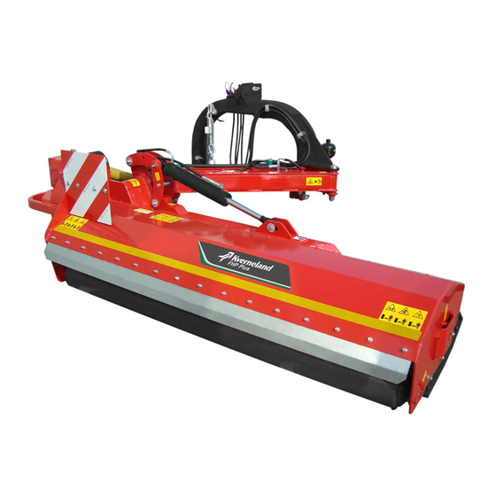
General description of the machine Main components A) Drive shaft mounting B) Support foot C) Front safety guards D) Rear deflector E) Slides F) lateral transmission hood G) PTO shaft guard H) Rear roller Cardan joint J) Three-point linkage Multiplier with PTO protection guard L) Joint for lateral movement H) Hydraulic cylinder for lateral movement N) Joint for machine alignment... -
Page 43: Accessories And Optionals
General description of the machine Accessories The choppers may be fitted with accessories on request, which can be ordered from your dealer. Accessories and Optional items requested after purchase of the machine must be fitted by the dealer. Optionals Counterblades The counterblade (A) improves the quality of work, breaking down the material in a more uniform manner. -
Page 44: Types Of Tools
General description of the machine Types of tools The various models are equipped with multi-purpose rotors, which means that it is possible to mount a wide range of tools. Blade Usage Recommended for cutting grass, Universal blade shrubs and plant stems. Particularly recommended for Hammer chopping orchard and vineyard... -
Page 45: Technical Data
Technical data Technical data Technical data Unit of Description measure Width (L) mm (in) 1823 (71.77”) 2123 (83.58”) 2273 (89.49”) Depth (P) mm (in) 2145 (84.45”) Height (H) mm (in) 1263 (49.72”) Working width mm (in) 1545 (60.83”) 1845 (72.64”) 1995 (78.54”) Min-max cutting height mm (in) - Page 46 Technical data Unit of Description measure Sound level measured db(A) < 70 in the driver's seat...
-
Page 47: Preliminary Operations
Preliminary operations Handling and Preliminary operations loading instruc- CAUTION tions Perform the handling and loading operations in accordance with the information supplied by the manufacturer, which can be found on the machine and in the user instructions. If necessary, the individuals authorised to perform these operations must prepare a “safety plan”... - Page 48 Preliminary operations WARNING Lifting and handling gear must be operated by personnel who are authorised and trained to use such equipment. The owner shall be responsible for ensuring the availability of suitable lifting gear, and of personnel who are qualified to operate it.
- Page 49 Preliminary operations CAUTION It is essential to ensure that the angle between the lifting chains and the vertical DOES NOT exceed 45°. An angle in excess of 45° will place considerable stress on both the slinging lines and the hooking points, so that there is a high risk of damage or breakages.
- Page 50 Preliminary operations 185-200...
- Page 51 Preliminary operations WARNING The hydraulic cylinder for lateral movement of the top link must be closed.
-
Page 52: Handling And Storage
Preliminary operations Handling and Transportation and lifting operations must be carried out by specialised firms that are active in the machinery transportation storage sector; it is not possible to guarantee complete safety when carrying out such operations, unless they are performed using the appropriate equipment, and by fully qualified personnel. - Page 53 Preliminary operations with packaging on pallet Unit of measur Width (W) mm (in) 1823 (71.77”) 2123 (83.58”) 2273 (89.49”) Weight with roller and Without kg (lb) 740 (1631.42) 780 (1719.6) 820 (1807.79) without PTO packagi Depth (D) mm (in) 2145 (84.45”) Height (H) mm (in) 1263 (49.72”)
-
Page 54: Preliminary Checks And Inspections
Preliminary operations Preliminary Upon receipt, perform a thorough inspection in order to make sure that there are no damaged parts or defects. checks and Also very the receipt of all the components necessary for its use, inspections including both standard and optional equipment. NOTICE If any damaged parts, defects, or deficiencies are encountered in relation to the machine, whether due to... -
Page 55: Machine-Tractor Combination
Preliminary operations machine-tractor The chopper models are equipped with a three-point linkage allowing the device to be hitched to the rear of the tractor only. combination The device is equipped with a hydraulic system for lateral movements (A) and for altering the tilt angle with respect to the three-point linkage (B). - Page 56 Preliminary operations Align the tractor with the machine, making sure that the latter is resting on the ground in a stable position. Insert the lower arms of the tractor hoist in the corresponding chopper hitching points (A). Lock the arms with the locking pins (B) and secure them with the lynch pins (C) inserting the washers (D) between them.
- Page 57 Preliminary operations NOTICE When the machine is connected to the tractor, verify that the direction of rotation of the PTO is as shown on the label affixed to the machine (ANTICLOCKWISE looking at the machine PTO from the rear). Adjusting the top link tie rod The upper attachments of the implement have a slot which allows the implement to absorb any differences in the evenness of the ground,...
- Page 58 Preliminary operations Connection of the PTO shaft WARNING Switch the engine off and ensure it is in the safe condition. Before getting down from the tractor: Disengage the power take-off. Lower all the tools to the ground. Set all controls to the neutral or park position. ...
- Page 59 Preliminary operations Carefully clean and lubricate the coupling on the PTO shaft (B) and the corresponding joint on the machine (C). Loosen and remove the retaining screw (A). Push the PTO shaft onto the joint on the machine. ...
- Page 60 Preliminary operations Carefully clean and lubricate the coupling on the PTO shaft (A) and the power take-off (B). Press button (C) or allow the PTO collar (D) to slide as shown in the figure. Slide the coupling onto the power-take-off until the shaft of the push-button (C) or the bearings in the collar are aligned with the groove on the shaft.
- Page 61 Preliminary operations Release the push-button or the collar while moving the coupling gently. Make sure that the push-button or collar bearings are inserted correctly in the groove on the shaft, and that the PTO shaft is connected correctly. Once the two ends of the PTO shaft have been connected, check that the two semi-protection panels rotate freely and independently, then connect the supporting chains for the protection tubes.
-
Page 62: Hydraulic Connection
Preliminary operations Hydraulic connection WARNING Before carrying out any maintenance on the hydraulic installation, turn off the tractor engine and depressurise the system! Hydraulic oil is dangerous, avoid all contact. Furthermore, highly pressurised oil easily penetrates skin and clothes and can cause serious injury. NOTICE The hydraulic system hoses are marked with the following information: maximum pressure, manufacturer, date of... - Page 63 Preliminary operations When making the connection, refer to the coloured caps used to protect quick-release couplings on the chopper tubes. A) Blue caps: device movement tubes B) Red caps: device rotation tubes.
-
Page 64: Adjustments
Preliminary operations Adjustments WARNING When carrying out these operations, personnel may be exposed to the risk of crushing, cutting and amputation: proceed with the utmost care and implement all the measures necessary to avoid hazardous situations. WARNING The machine and its components must be immobilised and placed on suitable supports. - Page 65 Preliminary operations Adjusting the position of the roller NOTICE The blades must be at least 3 cm from the ground when in operation. Proceed as follows: Raise the machine and block it in position. Unscrew and remove the screws (A) washers and nuts that secure the roller (B) at the ends.
- Page 66 Preliminary operations Adjustment of the To ensure correct support, deviceis fitted with two adjustable feet corresponding to the attachment for tractor coupling points. supporting feet Proceed as follows: Extract the safety pins (A). Extract the locking pins (B). ...
- Page 67 Preliminary operations Regulating the The device is equipped with a three-point linkage that can be used to move it laterally (A) depending on working requirements. lateral movement Simply activate the corresponding function on the tractor distributor to adapt the movement to the working requirements. WARNING Ensure that the device is not resting on the ground when carrying out this operation in order to avoid damaging it.
- Page 68 Preliminary operations Adjusting the tilt It is possible adjust the device tilt angle while it is in use in order to adapt it to the working requirements. angle Simply activate the corresponding function on the tractor hydraulic distributor. The tilt angle may be varied between -60° and 90° with respect to the horizontal.
-
Page 69: Uncoupling The Machine From The Tractor
Preliminary operations Uncoupling the machine from the WARNING tractor Turn off the engine, engage the parking brake, and remove the ignition key. Disconnect the machine in a level and stable area that can only be accessed by authorised operators, in such a way as not to create an obstacle. -
Page 70: Putting The Machine Back Into Service
Preliminary operations with original spare parts if necessary. Check that the PTO shaft is properly connected to the machine and that it is resting on the dedicated support with all the protection elements intact and working properly. Grease all the components fitted with greasers. ... -
Page 71: Placing The Machine In Storage
Preliminary operations Placing the machine in WARNING storage During the storage phase, make sure that the machine is in the safe condition. WARNING In order to avoid potential hazards for individuals and the environment, be sure to disconnect and render all the power sources unusable (electrical, pneumatic, hydraulic, etc.) and drain any liquids (lubricants, oils, etc.) that may be present. - Page 72 Preliminary operations WARNING In addition to being authorised and properly trained, if necessary, the operator must also perform certain manoeuvres in order to identify the main functions and controls when using the machine for the first time. Prior to use, the operator must check that the safety devices are properly installed and functioning.
- Page 73 Preliminary operations WARNING Never use the PTO shaft as a pedestal when performing any type of operation. Always disable the machine functions by deactivating the PTO when transporting it, especially on public roads. Make sure the nuts and bolts used to secure the main machine parts are tightened correctly at regular intervals.
-
Page 74: Road Travel
Preliminary operations Road travel WARNING Check that the width of the device is compatible with the applicable regulations regarding transport of agricultural equipment on the road. • The tractor driver must be legally authorised to perform the duties assigned to him/her. WARNING The device comes with a chain that must be fastened to the structure while driving on the road to avoid movements that... - Page 75 Preliminary operations CAUTION Before allowing the tractor to circulate on public roads with the machine connected to it, ensure that the following road use regulations are respected: • installation of illumination, indicator and protection devices • respect of transport widths/weights, loads per axle, load- bearing capacity of tyres and permitted total weights •...
- Page 76 Preliminary operations Page intentionally left blank...
-
Page 77: Using The Machine
Using the machine General warnings Before attempting to operate the machine, the user must read Using the machine and understand the preceding chapters, especially the section entitled “Safety”. WARNING Before starting and operating the machine, and while it is running, check the danger zone: the safety distances will vary depending on the size of the machine and any accessories that are mounted on it. - Page 78 Using the machine WARNING Pay particular attention when using on uneven and/or sloping terrain, or when close to ditches or banks. Adapt the speed and driving style to the conditions of the terrain. Always check the stability of the tractor and implement. Failure to ensure stable conditions when using the implement could cause serious accidents or death.
- Page 79 Using the machine NOTICE Only use the chopper horizontally when it is in its central configuration. Only use the chopper in an inclined position when it is laterally extended. DANGER It is forbidden to operate the device with the tractor astride a ditch.
- Page 80 Using the machine DANGER Danger of tipping. Do not use the device for support when working on inclined surfaces (ditches, slopes, etc.), as the tractor could tip over. WARNING Contact between the PTO and the device supporting structure. During operation, ensure the movements of the PTO remain within the device movement limits.
-
Page 81: Start-Up
Using the machine Start-up Raise the machine slightly so that it is not in contact with the ground when it starts. Insert the power- take-off and increase the rotation speed slowly. Lower the machine until it is in the working position and increase the speed of the power take-off until it reaches the working speed. -
Page 82: Obstruction
Using the machine Obstruction When working with vegetation that is too dense or too damp, or at an excessively high working speed, the implement may become clogged. In the event of clogging, the tractor engine speed will fall and the results will be affected. -
Page 83: Maintenance And Adjustments
Maintenance and adjustments Recommenda- Maintenance and adjustments tions for WARNING adjustments Except when expressly specified, every intervention and adjustment must be performed with the PTO disengaged, the tractor's engine off, the parking brake engaged, and the ignition key removed and in the driver's possession. WARNING All personnel authorised to carry out adjustments must take all the necessary precautions to perform them correctly and... -
Page 84: Recommendations For Part Replacements
Maintenance and adjustments Recommenda- tions for part WARNING replacements Except when expressly indicated, every intervention must be performed with the PTO disengaged, the tractor's engine off, and the ignition key removed and in the driver's possession. All personnel authorised to perform the aforementioned interventions must take the necessary precautions to ensure the safety of everyone involved, in full compliance with the current workplace health and safety requirements. -
Page 85: Scheduled Maintenance Intervals Chart
Maintenance and adjustments Scheduled The chart indicates all the maintenance intervals recommended by the manufacturer in order to maintain the machine in a good work maintenance condition and to prevent the excessive wear of each individual intervals chart component. All the indications in this manual are based on an average usage of the machine, in the case of more intensive use, for example by sub- contractors, select shorter intervals. -
Page 86: Lubricant Table
Maintenance and adjustments Lubricant table Important Use oils and lubricants with specifications identical to those indi- cated in the table. Operating width Specifications Parts to lubricate ENI BLASIA 320 upper transmission ISO-L-CKD Gearbox 1.2 lt 1.2 lt 1.2 lt DIN 51517 teil 3 CLP NLGI 2 DIN 51825 K2K-20 PTO shaft 150Brt. -
Page 87: Tightening Torque Table
Maintenance and adjustments Tightening torque Check all the fastening elements of the machine's various components with a torque wrench. Respect the torque values table indicated in the table.. CAUTION Replace any fastening elements that have deteriorated. NOTICE These values were obtained experimentally, and for serial applications it is recommended to check them by conducting field tests. -
Page 88: Lubrication And Greasing
Maintenance and adjustments Lubrication and greasing Greasing point diagram A) LH rotor bearing B) LH rotor bearing C) Cap D) RH roller bearing E) LH roller bearing F) Lateral movement joint G) Lateral movement joint H) Lateral movement joint Lateral movement joint J) Rotation joint K) Rotation joint L) Rotation joint... - Page 89 Maintenance and adjustments NOTICE The grease nipple for the rotor bearing on the lateral transmission side is located under to the lower cap on the transmission cover. WARNING Make sure the tractor's PTO is disengaged. Turn off the engine, engage the parking brake, and remove the ignition key.
-
Page 90: Cleaning The Machine
Maintenance and adjustments Handling oils and lubricants safely WARNING The additives present in lubricants may have harmful effects on health. Protect the skin with cream or safety gloves when handling lubricants. Lubricants may be harmful to health. In the event of skin injuries caused by lubricants, seek medical assistance immediately. - Page 91 Maintenance and adjustments WARNING These interventions must be performed by personnel with specific technical skills at workshops that are properly equipped and authorised by the manufacturer. WARNING The flexible hoses in the hydraulic system must be replaced every 6 years from the date of production, or earlier if signs of wear or degradation are encountered.
- Page 92 Maintenance and adjustments Page intentionally left blank...
-
Page 93: Malfunction Information
Malfunction information Problems - Causes • The purpose of the following information is to identify and correct Malfunction information any possible operational issues that may be encountered when - Solutions using the machine. • In the case of any anomalies that are not specified in the table, the operator can communicate these to the manufacturer in order to actively contribute to the development of new solutions, as well as technical and design improvements. - Page 94 Malfunction information Problem Cause Remedy Forward speed too high Reduce the travel speed Cutting height too low Adjust the cutting height Machine tears instead of cutting Excessive accumulation of cuttings cleanly, uneven distribution of Clean the chopper under the chopper chopped material Clean the machine from material Obstruction...
-
Page 95: Machine Maintenance
Machine maintenance Checking and Machine maintenance replacing the oil in WARNING the gearbox Make sure the tractor's PTO is disengaged. Turn off the engine, engage the parking brake, and remove the ignition key. In order to check the oil level it is necessary to remove the PTO protection guard (A), by removing the screws (B), the washers (C) and the retaining flange (D). - Page 96 Machine maintenance Topping up Position the machine horizontally on a flat surface. Unscrew the cap (A) in order to check the level. Unscrew the filler cap (C). Using a funnel, top-up using the oil indicated in the specifications until the level reaches the lower edge of the inspection hole (A).
- Page 97 Machine maintenance check the level. NOTICE Use oils with characteristics identical to those specified in the “Lubricant table”. CAUTION Never attempt to pour the oil out via the inspection cap by tilting the machine, as this could cause it to tip over, placing the operator and other personnel at risk of injury.
-
Page 98: Checking And Replacing The Blades
Machine maintenance Checking and The blades must be checked before each use of the machine. The quality of the cut and, above all, the safe operation of the machine replacing the depend on regular, thorough inspection of the blades. blades The blades must be replaced if: •... - Page 99 Machine maintenance To replace a blade, proceed as follows: Unscrew the bolt (A). Remove the old blade. Fit the new blade. Retighten the bolt (A) being careful to replace the washers correctly, if present; also replace the bolt if it shows signs of wear. ...
-
Page 100: Checking And Replacing The Belts
Machine maintenance Checking and replacing the belts WARNING Make sure the tractor's PTO is disengaged. Turn off the engine, engage the parking brake, and remove the ignition key. Checking Check the tension of the drive belts after the first 10 hours of use and subsequently every 30 hours, or when necessary. - Page 101 Machine maintenance Read the graduated scale on the body of the tool (B) at the exact point at which the upper surface of the indicator arm (C) crosses the scale (D). check the tension against the tensioning table provided with the tool.
- Page 102 Machine maintenance Adjusting the tension To adjust the tension of the drive belts, proceed as follows: remove the housing that covers the lateral transmission, unscrewing and removing the fixing screws and the respective washers Loosen the locknut (A) that secures the push rod in the adjusted position (B).
- Page 103 Machine maintenance Changing To replace the drive belts, reduce the tension until they can be removed. remove the housing that covers the lateral transmission, unscrewing and removing the fixing screws and the respective washers Loosen the locknut (A) that secures the push rod in the adjusted position (B).
-
Page 104: Replacing The Skid Runners
Machine maintenance Replacing the skid The runners protect the device from coming into direct contact with the ground. These tend to wear out, and must be replaced promptly in runners order to avoid damage to other parts of the implement. WARNING Make sure the tractor's PTO is disengaged. -
Page 105: Cleaning In The Case Of Clogging
Machine maintenance lock the screws with new nuts. Cleaning in the case of clogging DANGER Make sure the tractor's PTO is disengaged. Turn off the engine, engage the parking brake, and remove the ignition key. Remove build-ups using a suitable wooden or metal lever. WARNING Do not carry out this operation by hand. - Page 106 Machine maintenance Page intentionally left blank...
-
Page 107: Ec Declaration Of Conformity
Number plate and FM - FML - FHS - FRO - FXE - FRD - FRH - FHP - FHPplus - FXN CE marking - FXZ - FXF - FX - FXJ... - Page 108 EC Declaration of Conformity Page intentionally left blank...
-
Page 109: Ukca Declaration Of Conformity
Number plate and FM - FML - FHS - FRO - FXE - FRD - FRH - FHP - FHPplus - FXN marking - FXZ - FXF - FX - FXJ... - Page 110 UKCA Declaration of Conformity Page intentionally left blank...
-
Page 111: Index
Index Index Accessories and Optionals Handling and loading instructions Adjusting the position of the roller Handling and storage Adjusting the tension Handling oils and lubricants safely Adjusting the tilt angle Hydraulic connection Adjusting the top link tie rod Adjusting the working height Adjustment of the supporting feet Adjustments Identificazione costruttore e macchina... - Page 112 Index Recommendations for part replacements Recommendations for use and operation Reference operators Regulating the lateral movement Replacing the skid runners Residual risks Road travel Safety devices on board the machine Safety regulations for loading and unloading Safety regulations for maintenance and adjustments Safety regulations for road travel Safety regulations for use and operation Safety rules for the protection of the environment 30...
Need help?
Do you have a question about the FHP and is the answer not in the manual?
Questions and answers