
Related Manuals for Kverneland a-drill


Summary of Contents for Kverneland a-drill
- Page 1 Pneumatic seed drill a-drill Operating manual Translation of the original operating manual Issue 04/2018 Printing 02.2018 Language From serial no. RFSDCxx006315 Execution Accessories Reference RF31913...
- Page 2 The copyright and use (Copyright) are held by the Kverneland Group Les Landes Génusson SAS, France. Copying, transfer to other media,translation or even partial use of this text are unlawful without the written authorization from Kverneland. All rights reserved. The content of...
-
Page 3: Table Of Contents
Table of contents Table of contents Preamble ........... Adjustments ..........Target group for this operating manual Using the seed drill with the box 3.2 Meaning of symbols Adjustments ..........Using the seed drill with the box 5.2 Safety ............For your safety Changing the flow during Warning symbols operation... -
Page 4: Preamble
Preamble Target group for This operating manual is intended for trained farmers and individuals Preamble who are otherwise qualified to perform agricultural activities, this operating and who have received training in the operation of this machinery. manual For your safety Study the contents of this operating manual carefully before assembly or initial operation of this machine. -
Page 5: Safety
Safety For your safety In this chapter, you will find the general safety instructions. The Safety different chapters in this operating manual include specific safety instructions. Please follow these safety instructions: • in the interest of your own safety, • in the interest of the safety of others, •... -
Page 6: Warning Symbols
Safety Warning symbols On this machine, you will find safety decals for user safety. These decals must not be removed. When these are illegible or they no longer stick, order new decals and affix them at the corresponding locations. Meaning of safety symbols Read and comply with the manual and safety instructions before starting up or carrying out any operations on the machine. -
Page 7: Safety Regulations
Safety Safety regulations Maintenance The brakes or vehicle immobilisation system must be engaged before all interventions within the radius of the tractor - tool unit. Wear safety gear (helmet, safety shoes, gloves, etc.) when changing parts on the machine. You are advised to be careful with all parts with sharp edges or corners. -
Page 8: Presentation Of The Accessory
Modifications to the tool made by the client or the use of spare parts or accessories that are not from KVERNELAND will cancel the manufacturer's liability for all damages resulting from the modification. The company will not be held liable for damage resulting from... -
Page 9: General Description
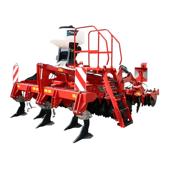
Presentation of the accessory General Description Hopper (200 or 500 l) Walkway (access filling and settings) Blower (electrical or hydraulic) Spreader rail (in front of the roller) -
Page 10: Type Of Seed Drills
Presentation of the accessory Type of Seed drills The a-drill pneumatic seed drills are distribution seed drills by fixed grooved rotors. The seed drill does not contain sowing elements, broadcast sowing is carried out by 8 spreaders. The flow adjustment is by variation in the grooved rotor speed, 8 rotors are available. - Page 11 Presentation of the accessory 8 grooved distribution rotors are available : Series / Rotor Type of rotor Reference Application option fb-f-fb-fb Fine grooves: Sowing of small seeds or small fine dummy Standard RF32066 quantities. fine equipment Eg: mustard, rapeseed, clover, fine dummy phacelia, slug pellets, etc.
-
Page 12: Rigid Clc
Delivery and assembly Rigid CLC Delivery and assembly Mounting the support and the hopper Task description There are two types of mountings: • Mounting with the hopper centred compared to the machine. • Mounting with the hopper offset compared to the machine. During offset mounting, it is necessary to move it 14 cm to the left (compared to the machine driving direction) on the following models: •... - Page 13 Delivery and assembly Procedure Turn the hopper so that the hoses come out from the rear of the machine. Using U clamps, fix the support to the second beam of the main frame. Use the four long fixing screws. ...
- Page 14 Delivery and assembly CLC 3 rows 3m00 (9’10”) CLC 2 rows 4m00 (13’1”) 545 mm ” 570 mm ” 7/16 CLC 3 rows 3m50 (11’6”) CLC 3 rows 4m00 (13’1”) 600 mm 480 mm ” ”...
- Page 15 Delivery and assembly Mounting the walkway Procedure Guardrail Reinforcement crossbar Upper part of stairs Lower part of stairs Fixing brackets Ball screw Position the support arms for the walkway on the frame, respecting the dimensions indicated on the diagrams page 13. ...
- Page 16 Delivery and assembly Mounting diagrams for the platform CLC Evo CLC Pro 3 rows 2 rows ” ” 20” ” ” 9/16 ” 7/16 ” 9/16 ” ” 13 ” 9/16 ” 18 ” ” 9/16 ” 9/16 ” ” ”...
- Page 17 Delivery and assembly Positioning the spreaders Task description The spreaders must be distributed in a regular way on the machine, although their position can be slightly offset depending on the machines. The following table provides the mounting dimensions for the different machines: Machine 355 / 14”...
- Page 18 Delivery and assembly Procedure Levelling tines fixed to the roller beam: Install the rail of spreaders in the lower position on the support.
- Page 19 Delivery and assembly Adaptation on a machine equipped with levelling discs: Fix the roller supports to the last 2 fixing holes of the parallelogram (A). Use and adapt the longest push bar (B) in order to keep the working angle of the levelling discs.
- Page 20 Delivery and assembly Passage of hoses Order of hose distribution for seed flow Ensure that you respect the seed outlet numbers compared to the spreader positions Hose 3 Hose 2 Hose 1 Hose 4 Hose 4 Hose 3 Hose 2 Hose 1 Hose passage point on the left side (the right side...
- Page 21 Delivery and assembly Hose supports have been designed to allow optimal passage of hoses on the machine. Fix the supports above the arms. Group the hoses and pass them in the supports. Cross the hoses when you connect them to the rail of spreaders. The hoses that come out of the centre of the seed drill must supply the exterior spreaders of the machine.
-
Page 22: Delivery And Assembly
Delivery and assembly Folding CLC Delivery and assembly Mounting the hopper support Task description On folding cultivators, the hopper support and the access walkway are fixed to the central frame using 4 screws. Procedure Align the holes located at the rear extremity of the hopper support (B) with the rear extremity of the central frame (A) of the machine. - Page 23 Delivery and assembly Mounting the hopper Task description Once the support is fixed to the machine, you now need to mount the hopper onto it. The hopper is placed on the support and fixed using 14 screws. Procedure Place the hopper on the support fixing plate, aligning the screw holes.
- Page 24 Delivery and assembly Positioning the spreaders Task description The spreaders must be distributed in a regular way on the machine, although their position can be slightly offset depending on the machines. The following table provides the mounting dimensions for the different machines: Machine 490 / 19 530 / 20...
- Page 25 Delivery and assembly Passage of hoses Order of distribution for seed hoses on CLC Pro Ensure that you respect the seed outlet numbers compared to the spreader positions. CLC PRO Hose 1 Hose 2 Hose 3 Hose 4 Hose 4 Hose 3 Hose 2 Hose 1...
- Page 26 Delivery and assembly Order of distribution for seeds on CLC Evo Ensure that you respect the seed outlet numbers compared to the spreader positions. CLC Evo equipped with a parallelogram Hose 4 Hose 3 Hose 2 Hose 1 CLC Evo equipped with a roller arm Hose 4 Hose 3 Hose 2...
- Page 27 Delivery and assembly Use the support containing a spring (A). Install the spring support on the exterior arm, ensuring that the spring is directed towards the interior of the machine. Fix the support using a metal clamping ring. ...
-
Page 28: Delivery And Assembly
Delivery and assembly Rigid Qualidisc Delivery and assembly Mounting the hopper support and the hopper Procedure Turn the hopper so that the hoses come out from the rear of the machine. Using U clamps (A), fix the support to the second beam of the main frame. - Page 29 Delivery and assembly Mounting the walkway Platform Retractable step Walkway extension Guardrail Brackets Roller beam Procedure Centre the support for the walkway on the roller beam (F). Position the two brackets (E) on the roller beam. Bolt the brackets. Machines equipped with double rollers: ...
- Page 30 Delivery and assembly Positioning the spreaders Task description Different accessories such as a comb harrow or rollers can be mounted on disc cultivators. The tool has no effect on the mounting of the spreader rail. The spreaders must be distributed in a regular way on the machine, although their position can be slightly offset depending on the machines.
- Page 31 Delivery and assembly Passage of hoses Order of distribution for The seed flow hoses leave the hopper to the front when it is mounted seed hoses on a rigid mounted disc cultivator. Cultivators 3m00 (9’10”) and 3m50 (11’6”) Hose 4 Hose 3 Hose 2 Hose 1...
- Page 32 Delivery and assembly Cultivators 4m00 (13’1”) Hose 4 Hose 3 Hose 2 Hose 1 Ensure you respect the seed outlet numbers compared to the spreader positions. Group the 4 hoses (position B) so that they form a square. ...
- Page 33 Delivery and assembly Length of hoses 3m00 (9’10”) 3m50 (11’6”) 4m00 (13’1”) 2600 mm / 102” 3100 mm / 122” 3400 mm / 134” Hose 1 2900 mm / 114” 2700 mm / 106” 2900 mm / 114” Hose 2 2400 mm / 94”...
-
Page 34: Delivery And Assembly
Delivery and assembly Folding Qualidisc Delivery and assembly Mounting the hopper support Task description On folding cultivators, the hopper support and the access walkway are fixed to the central frame using 4 screws. Procedure Align the holes located at the rear extremity of the hopper support (B) with the rear extremity of the central frame (A) of the machine. - Page 35 Delivery and assembly Positioning the spreaders Task description The spreaders must be distributed in a regular way on the machine, although their position can be slightly offset depending on the machines. The following diagrams specify the mounting dimensions (mm/in) for the different machines: Disc cultivators 4m00 Marking 4m00 (13’1”)
- Page 36 Delivery and assembly Disc cultivators 5m00 (16’5”) Disc cultivators 6m00 (19’8”)
- Page 37 Delivery and assembly Marking 5m00 (16’5) 6m00 (19’8) Marking 5m00 (16’5) 6m00 (19’8) A1 & A2 1060 / 42” 1590 / 63” K1 & K2 307 / 12 665 / 26 ” ” 11/16 3/16 974 / 38 974 / 38 L1 &...
- Page 38 Delivery and assembly Passage of hoses Order of distribution for seed hoses Ensure that you respect the seed outlet numbers compared to the spreader positions. Hose 1 Hose 2 Hose 3 Hose 4 Mounting the hose supports: Thread the spring support (B) into the jack retention screw. ...
- Page 39 Delivery and assembly Passage of hoses: Group the 4 hoses using clamping rings (E). Connect the hose n°1 to the spreader. Pass hoses n°2,3 and 4 through the hose support (A). Group hoses n°2,3 and 4 using clamping rings. ...
-
Page 40: Rigid Qualidisc Farmer
Delivery and assembly Rigid Qualidisc Delivery and assembly Farmer Mounting the hopper support and the hopper Procedure Turn the hopper so that the hoses come out from the rear of the machine. Using U clamps (A), fix the support to the second beam of the main frame. - Page 41 Delivery and assembly Mounting the walkway Platform Retractable step Walkway extension Guardrail Brackets Roller beam Procedure Centre the support for the walkway on the roller beam (F). Position the two brackets (E) on the roller beam. Bolt the brackets. Machines equipped with double rollers: ...
- Page 42 Delivery and assembly Positioning the spreaders Task description Different accessories such as a comb harrow or rollers can be mounted on disc cultivators. The tool has no effect on the mounting of the spreader rail. The spreaders must be distributed in a regular way on the machine, although their position can be slightly offset depending on the machines.
- Page 43 Delivery and assembly Passage of hoses Order of distribution for The seed flow hoses leave the hopper to the front when it is mounted seed hoses on a rigid mounted disc cultivator. Cultivators 3m00 (9’10”) and 3m50 (11’6”) Hose 4 Hose 3 Hose 2 Hose 1...
- Page 44 Delivery and assembly Cultivators 4m00 (13’1”) Hose 4 Hose 3 Hose 2 Hose 1 Ensure you respect the seed outlet numbers compared to the spreader positions. Group the 4 hoses (position B) so that they form a square. ...
- Page 45 Delivery and assembly Length of hoses 3m00 (9’10”) 3m50 (11’6”) 4m00 (13’1”) 2900 mm / 114” 3100 mm / 122” 3300 mm / 130” Hose 1 2500 mm / 98” 2600 mm / 102” 2400 mm / 94” Hose 2 2200 mm / 87”...
-
Page 46: Folding Qualidisc Farmer
Delivery and assembly Folding Qualidisc Delivery and assembly Farmer Mounting the hopper support Task description On folding cultivators, the hopper support and the access walkway are fixed to the central frame using 4 screws. Procedure Align the holes located at the rear extremity of the hopper support (B) with the rear extremity of the central frame (A) of the machine. - Page 47 Delivery and assembly Mounting the hopper Task description Once the support is fixed to the machine, you now need to mount the hopper onto it. The hopper is placed on the support and fixed using 14 screws. Procedure Place the hopper on the support fixing plate, aligning the screw holes.
- Page 48 Delivery and assembly Positioning the spreaders Task description The spreaders must be distributed in a regular way on the machine, although their position can be slightly offset depending on the machines. The following diagrams specify the mounting dimensions (mm/in) for the different machines: Disc cultivators 4m00 (13’1”) O1 O2 Marking...
- Page 49 Delivery and assembly Disc cultivators 5m00 (16’5”) Q1 Q2 Marking 5m00 (16’5”) Marking 5m00 (16’5”) A1 & A2 1025 / 40” L1 & L2 190 / 7 ” 1039 / 41” M1 & M2 395 / 15 ” 9/16 C1 & C2 285 / 11 N1 &...
- Page 50 Delivery and assembly Disc cultivators 6m00 (19’8”) Markin 6m00 (19’8”) Marking 6m00 (19’8”) A1 & A2 1525 / 60” K1 & K2 665 / 26 ” 3/16 1039 / 41” L1 & L2 95 / 3 ” C1 & C2 385 / 15 M1 &...
- Page 51 Delivery and assembly Passage of hoses Order of distribution for seed hoses Ensure that you respect the seed outlet numbers compared to the spreader positions. Hose 1 Hose 2 Hose 4 Hose 3...
- Page 52 Delivery and assembly Mounting the hose supports: Thread the spring support (B) into the jack retention screw. Thread the pin into the jack retention screw. Place the jack retention screw into the hole located on the interior roller arm.
- Page 53 Delivery and assembly Passage of hoses: At the hopper outlet, connect the hose n°1 to the spreader. Pass hoses n°2,3 and 4 through the hose support (A). At the hose support exit, group the 3 hoses using clamping rings. ...
-
Page 54: Delivery And Assembly
Delivery and assembly Equipment available on Delivery and assembly mounted machines Rigid machines End of Field sensor (A) The end of field sensor stops distribution when you raise the machine to turn. Distribution automatically restarts when you lower the machine. ... - Page 55 Delivery and assembly Folding machines End of Field sensor (A) The end of field sensor stops distribution when you raise the machine to turn. Distribution automatically restarts when you lower the machine. Install the end of field sensor on the machine upper link coupling. ...
-
Page 56: Delivery And Assembly
Delivery and assembly Qualidisc T Delivery and assembly Mounting the hopper support Task description The hopper is mounted on an articulated support attached to the transportation carrier. In this way, the seed drill is always horizontal whether the machine is lowered or raised. Procedure ... - Page 57 Delivery and assembly Mounting the walkway Task description The seed drill is accessed from the rear of the machine via the stairs and the walkway. Adjustments to the seed drill are carried out either by the walkway or the ground by the rear of the machine. Procedure ...
- Page 58 Delivery and assembly Positioning the spreaders Task description Different accessories such as a comb harrow or rollers can be mounted on disc cultivators. The tool has no effect on the mounting of the spreader rail. The spreaders must be distributed in a regular way on the machine, although their position can be slightly offset depending on the machines.
- Page 59 Delivery and assembly Compact trailed discs cultivator - 5m00 (16’5”) Marking 5m00 (16’5) Marking 5m00 (16’5) A1 & A2 1060 / 42” 217 / 8 ” 1024 / 40” J1 & J2 362.5 / 14 ” C1 & C2 88 / 3 K1 &...
- Page 60 Delivery and assembly Compact trailed discs cultivator - 6m00 (19’8”) Marking 6m00 (19’8”) Marking 6m00 (19’8”) A1 & A2 1590 / 63” 20 / 3/16” 1024 / 40” I1 & I2 385 / 16 ” 3/16 C1 & C2 1350 / 53” J1 &...
- Page 61 Delivery and assembly Compact trailed discs cultivator - 7m00 (22’12”) Marking 7m00 (22’12”) Marking 7m00 (22’12”) A1 & A2 1590 / 63” 20 / 3/16” 1024 / 40” I1 & I2 370 / 14 ” C1 & C2 1700 / 67” J1 &...
- Page 62 Delivery and assembly Passage of hoses Order of distribution for seed hoses Ensure that you respect the seed outlet numbers compared to the spreader positions. Hose 4 Hose 3 Hose 2 Hose 1 Length of hoses 4m00 (13’1”) 5m00 (16’5”) 6m00 (19’8”) 7m00 (20’12”) 3110 / 122”...
-
Page 63: Equipment Available On Qualidisc T
Delivery and assembly Passage of hoses At the hopper outlet, pass the 4 hoses in the guide located on the carrier. Connect hoses n°4 and 3 to the spreaders. Pass hose n°1 in the upper bracket of the hose support. ... -
Page 64: Ctc
Delivery and assembly Delivery and assembly Mounting the hopper support Task description The hopper support is fixed to the rear of the central frame. Procedure Position the hopper support to the rear of the central frame of the machine. ... - Page 65 Delivery and assembly Mounting the hopper Procedure Turn the hopper so that the hoses come out from the front of the machine. Place the hopper on the support. Align the fixing holes. Position the 10 screws M12x80 (A) on the sides of the support. ...
- Page 66 Delivery and assembly Positioning the spreaders Task description The spreaders must be distributed in a regular way on the machine, although their position can be slightly offset depending on the machines. The direction of the spreaders is optimal when the hoses are in contact with the roller beam.
- Page 67 Delivery and assembly Trailed tine cultivator - 5m00 (16’5”) Trailed tine cultivator - 6m00 (19’8”) Marking 5m00 (16’5”) 6m00 (19’8”) Marking 5m00 (16’5”) 6m00 (19’8”) A1 & A2 100 / 3 100 / 3 E1 & E2 1250 / 49” 497 / 19 ”...
- Page 68 Delivery and assembly Passage of hoses Order of distribution for seed hoses Hose 4 Hose 3 Hose 2 Hose 1 Ensure that you respect the seed outlet numbers compared to the spreader positions. Length of hoses 4m00 (13’1”) 5m00 (16’5”) 6m00 (19’8”) 3200 / 126”...
- Page 69 Delivery and assembly Passage of hoses At the hopper outlet, connect the hose n°4 to the spreader. Group the 3 remaining hoses in position A. Attach the 3 hoses to the chain using clamping rings. Connect the hose n°3 to the spreader. ...
-
Page 70: Equipment Available On Ctc
Delivery and assembly Equipment available on Delivery and assembly The end of field sensor The end of field sensor (A) is installed on the lifting jack. It is an inductive type sensor, and detects the sliding rod (B) fixed on the jack. When the rod leaves the detection range of the sensor, the seed drill distribution is cut-off. -
Page 71: Mounting Kit For Hopper Only
Delivery and assembly Mounting kit for This kit is designed to facilitate the installation of the seed drill on your Delivery and assembly machine. It includes the following elements: hopper only • The hopper. • The adaptation plate for your machine. •... -
Page 72: Adjusting The Machine
Adjusting the machine Lifting sensor Adjusting the machine Mounted machines Operations When the machine is coupled and raised, the upper link bar presses on the sensor rod. The sensor sends an interruption signal to the seed drill, which stops all seed distribution. Rigid Folding Sensor support plate... - Page 73 Adjusting the machine Trailed machines The raising sensor is positioned on on of the lifting jacks of the machine transportation carrier. The sensor detection rod is located on the jack rod. By default, when the rod passes in front of the sensor, the seed drill stops the distribution.
-
Page 74: Hydraulic Blower
Adjusting the machine Hydraulic blower The adjustment of the hydraulic blower is an important task that must be carried out carefully. Failure to respect the following instructions could lead to machine damage. • The adjustment must be as precise as possible to avoid sowing defects in case of low revving or damage to the blower in case of over-revving. - Page 75 Adjusting the machine Adjustment variant n°2 The tractor is equipped with an adjustable flow distributor. Loosen the adjustment knob to the maximum (A). On the tractor flow regulator, adjust the oil level to 0. Switch on the blower. ...
-
Page 76: Seed Drill Adjustment
Seed drill adjustment Distribution Seed drill adjustment Choice of distribution The choice of distribution rotor depends on the sowing required. Consult the sowing tables (page 80) as well as the list of distribution rotor rotors (page 11) to choose the most suitable rotor. To replace the distribution rotor, proceed as follows : ... - Page 77 Seed drill adjustment Hopper bottom sheet Always remove the hopper bottom sheet to avoid damaging the distribution wheels when sowing large seeds : • Vetch, • peas, • beans, • etc. We also recommend using Flex distribution rotors as these are flexible and do not break.
- Page 78 Seed drill adjustment Adjusting the brush A brush is mounted on the distribution rotor to regulate the seed flow. The distance between the brush and the distribution rotor is adjusted using a lever (A) attached to the seed drill frame. The lever can be adjusted on a scale (B) from -5 (position closed to the rotor) to +4 (position furthest from the rotor).
- Page 79 Seed drill adjustment Working width / The sowing quantity depends on the speed of the distribution rotor. It can be adjusted manually with the box 3.2 or automatically depending sowing table on the working speed with the box 5.2 and a speed sensor. To define the quantity of seeds to sow, carry out a fixed position test before starting work.
- Page 80 Seed drill adjustment Sowing tables...
- Page 81 Seed drill adjustment...
- Page 82 Seed drill adjustment...
- Page 83 Seed drill adjustment...
- Page 84 Seed drill adjustment...
- Page 85 Seed drill adjustment...
- Page 86 Seed drill adjustment Pre-adjustment of Take the result of your calculation (the formula can be found page hydraulic motor Define the seed category used with the following table: Seed cate- Seed cate- Description Description gory gory Rapeseed Physiostart Poppy Buckwheat Alfalfa...
- Page 87 Seed drill adjustment Sowing width of 4m00 and 5m00 (13’1” and 16’5”) Seed dosage (Kg/min) Sowing width of 6m00 and 7m00 (19’8” and 22’12”) Seed dosage (Kg/min) Example: Sowing width of 6m00 (19’8”). 4Kg/min in category “1”, tighten the valve to the maximum then loosen 5 turns.
-
Page 88: Filling The Seedbox
Filling the seedbox Safety Filling the seedbox In order to avoid any accident, make sure the machine is on the ground before filling the seedbox Folding CLC CLC PRO CLC EVO Fold the machine to get to the seedbox. ... -
Page 89: Qualidisc And Qualidisc Farmer
Filling the seedbox Qualidisc and Qualidisc Farmer Unfold the machine. Fill in the seedbox. -
Page 90: Adjustments
Adjustments Using the seed drill with Adjustments the box 3.2 Description of the control module Displays the actual rotor rotation speed as a percentage of its maximum speed (from 1 to 99%). Box power on indicator. Lights if the box is activated. "On/Off"... -
Page 91: Adjustments
Adjustments Use in the field Press on button XX to switch on the distribution. The control indicator above the button XX flashes. This indicates that the blower is starting. After a few seconds, the control light above the button XX lights continuously. - Page 92 Adjustments Emptying the hopper The hopper emptying is operated on the opposite side to the hose connection to the seed drill. Follow this procedure: Unscrew the knobs located on the distribution sheet. Turn the sheet and place it on the lower sheet so that it can be used as a slide for the seeds.
- Page 93 Adjustments Charging the box battery when on may lead to voltage peaks. This may damage the electrical equipment in the box. In case of problems Problem Possible solution Check whether the power supply cable is correctly plugged into the box. Having pressed on button XX, nothing ...
-
Page 94: Using The Seed Drill With The Box
Adjustments Using the seed drill with Adjustments the box 5.2 Control module Graphic display of seed drill parameters Box power on indicator. Lights if the box is activated. "On/Off" button: Activates or deactivates the box. Activate or deactivate the blower. •... - Page 95 Adjustments Main display Organisation of the menus...
- Page 96 Adjustments Start screen • Indicates the type of box. In this case: 5.2 • Indicates the software version installed. • This information is essential for correct maintenance operations by the technical services. Operations without speed sensor Distribution rotor rotation speed, defined as SW % 25.0 a percentage of the maximum rotor speed.
- Page 97 Adjustments Selection menu Tabs in the main menu SW % 25.0 Total area: Calibrate 12.07 ha Calibration test ? 10.0 km/h 20.0/ Speed ? Area: kg/ha 3.93 ha Sprache Language Operating voltage: Total hours: Langue 23.46 h 11.7 V Seed removal I-1: I-2: Hours:...
- Page 98 Adjustments Procedure Seed drill preparation Unscrew the two knobs (A) located on the distribution sheet (B). Re-install the lower plate (C) to accentuate its slope. Attach the lower plate in position on the frame using the knob (D) located to the right.
- Page 99 Adjustments After the test When the test is finished, remove the bag or recipient and weigh it. Input : Enter the weighed value (8). • Calibr value If the difference between the weighed value and the theoretical value indicated is less than 3%, the following screen is displayed: 3.25 kg Input :...
- Page 100 Adjustments Calibration of travel speed It is necessary to carry out a calibration as the box uses these values as a base to do the calculations (display of speed, dosing, calculation of surfaces, etc.) Test distance The test distance is 100 metres (328’) ...
- Page 101 Adjustments Manual calibration The calibration can be carried out without travelling 100 metres (328’). In the main menu of the box, choose the tab “Speed calibration?”. Calibrate Press on XX to select this tab. Speed ? Choose "Manual". ...
- Page 102 Adjustments Emptying the hopper Hopper emptying may be necessary at the end of work, or when changing seeds or the distribution rotor. The hopper emptying is operated on the opposite side to the hose connection to the seed drill. Follow this procedure: ...
-
Page 103: Changing The Flow During Operation
Adjustments Languages Seed drills equipped with an electrical blower Language In the main menu of the box, choose the required language. Sprache Press on XX to validate. Langue Select the required language. Press on XX to validate the selection. Seed drills equipped with a hydraulic blower ... - Page 104 Adjustments Status and trouble- shooting messages Warning messages Display Cause Solution Internal VCC (5V) The box supply voltage is too weak. Return the box to the factory. not OK ! Reduce the number of devices connected Operating to the tractor. voltage ...
- Page 105 Adjustments Display Cause Solution Appears when the duration of the calibration is Press and hold the distribution switch for too short. longer (at least 20 seconds). Compare with the pre-defined adjustments. The driving speed is too high Tractor speed ...
- Page 106 Adjustments Error messages Display Cause Solution Check the cabling. Operating • Check the connectors. voltage The operating voltage is too low. • Check the tractor alternator. Excessive voltage deviations occur. not OK ! Stop other devices connected to the tractor battery (work projector, etc.).
- Page 107 Adjustments Display Cause Solution Check the state of the cables and sockets. The box does not receive a signal from the If no malfunctions are detected with the Ground wheel speed sensor ground wheel, contact the After Sales Service.
-
Page 108: Trouble-Shooting
Adjustments Trouble-shooting Problem Cause Solution The distribution rotor turns when the Incorrect signal from the lifting Change the position of the lifting machine is raised. mechanism. mechanism sensor. • Switch on the distribution rotor The distribution rotor is not manually. - Page 109 Adjustments Problem Cause Solution • Incorrect calibration. The flow in kg/ha or in grains/m² is • The values have been changed in Perform a calibration. not displayed. the calibration menu. Check the surface counter. • Check the working speed. Incorrect speed.
-
Page 110: Maintenance
Maintenance For your safety Maintenance Special Safety instructions Conditions required for maintenance work Carry out maintenance work only if you have the necessary knowledge and if you have appropriate tooling. A lack of knowledge or inappropriate tools may lead to accidents. Use original spare parts Use only original spare parts for components related to safety. -
Page 111: Guarantee
Guarantee At delivery of the tool, check that all the accessories are included and Guarantee that there is no damage due to transport. Claims must be made in writing within 6 days. The guarantee will be granted only if the conditions appearing on the delivery contract have been met by the buyer. -
Page 112: Disposal Of The Tool
Disposal of the tool When the service life of your tool is over, it must be properly disposed Disposal of the tool of. Please observe applicable regulations when disposing of the tool. Do not spread on the ground or pour into the sewers used grease or other substances such as motor oil, hydraulic oil,coolant fluid, brake fluid, fuel... -
Page 113: Conformity Declaration
Conformity declaration In accordance with Conformity declaration Kverneland Group Les Landes Génusson SAS directive 2006/42/EC 9 Rue du Poitou FR-85130 Les Landes Genusson declare under our sole responsibility that the product Pneumatic seed drill a-drill to which this declaration relates, corresponds to instructions in terms of health and safety stipulated in the European directive 2006/42/EC. -
Page 114: Index
Index Index Symbols 7 terminal cable Intensity current Agitator Languages Blower Box 3.2 Main display Box 5.2 Main menu Bracket Maximum pressure Branch cable Metal parts Mounted machines Control box Current Operating intensity voltage Distribution Pictograms test pictograms Platform Pneumatic seed drill Electrical blower Electrical supply... - Page 115 Index Symbols Test distribution Tractor speed information cable Trailed machines Type of Seed drills User safety User safety Version 3.2 Version 5.2 Voltage operating Walkway...
Need help?
Do you have a question about the a-drill and is the answer not in the manual?
Questions and answers