
Related Manuals for Kverneland 150 Series


Summary of Contents for Kverneland 150 Series
- Page 1 150 Series Operating manual Original operating manual Edition 2014 Date of print 06.2018 Language Machine number Model 150 Series Document number A133084640.EN...
- Page 2 Copyright by Kverneland Group Operations Norway AS. Reproduction, transfer to other media, translation or the use of extracts or parts of this manual without the explicit permission of Kverneland, is not permitted. All rights reserved. The contents of this operating manual are subject to...
-
Page 3: Table Of Contents
Table of contents Table of contents Preface ............Lubrication Target group for this operating manual Replace hoses Symbols used Replace wearing parts Terminology used Replacing Quick- fit points Replacing Knock-on® points Safety ............Tighten bolts and nuts Safety decals Tightening torque of the hydraulic General safety information connections Getting to know the plough ..... -
Page 4: Preface
Preface Preface Target group for This operating manual is aimed at those concerned with the control, use and maintenance of the machine. It contains all the data required this operating for safe handling, use and maintenance of the plough. manual For your safety Before starting to adjust and use your plough, familiarise yourself with this operating manual. -
Page 5: Terminology Used
Preface Terminology used In this operating manual the following terminology is used: • Turned to the right: observed from the rear, all bodies are located on the right side of the frame. • Turned to the left: observed from the rear, all bodies are located on the left side of the frame. -
Page 6: Safety
Safety This chapter contains general safety instructions for this product. Each Safety chapter of the operating manual contains additional specific safety in- formation. Safety decals For your safety, safety decals are placed on important parts of the plough. Please do not remove them. If they become illegible or begin to peel off, replace them with new decals (see the spare parts cata- logue). - Page 7 Safety Meaning The meaning of the safety decals is explained below. Read the operating manual and follow the instructions. The plough must only be used for the first time once the operating manual has been read and understood. Do not stand between the tractor and the plough Standing between the tractor and plough increases the risk of being crushed.
-
Page 8: General Safety Information
Safety General safety Please read and ensure you understand the following general safety information. Specific safety information is pointed out in the relevant information chapters. General Read and ensure you understand the instructions Before starting to operate the plough, read the operating manual and follow the instructions. - Page 9 Safety Coupling Risk of injury when coupling There is an increased risk of injury when the plough is coupled to the tractor. Therefore: • Secure the tractor to prevent it from rolling. • Do not stand between the tractor and plough when coupling •...
- Page 10 Use only genuine Kverneland spare parts. Other products may ad- versely affect the correct operation of the plough and safety. The war- ranty will no longer be valid if parts not produced by Kverneland are used. Check the tyre pressure Regularly check to ensure the tyre pressure meets the requirements.
-
Page 11: Getting To Know The Plough
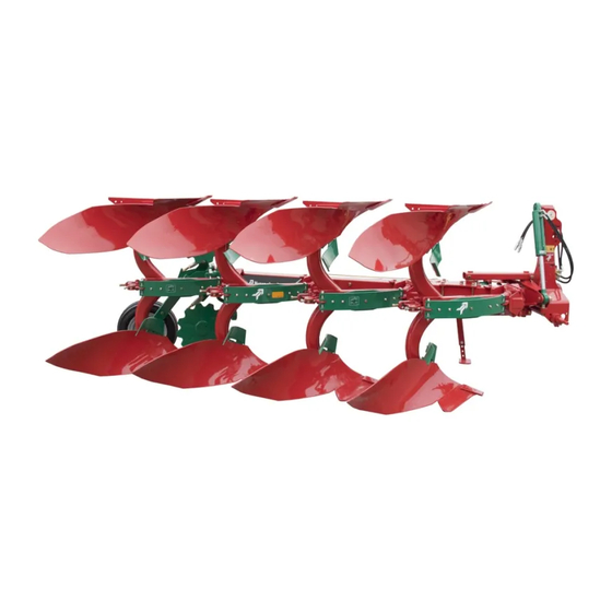
Complete range of bodies A complete range of plough bodies is available for all requirements. Kverneland plough bodies offer excellent ploughing quality, are wear resistant and have a low draft requirement. Robust turning head The plough's turning head is designed to have the centre of gravity close to the tractor, thus minimising the lifting requirement as much as possible. -
Page 12: Components
Getting to know the plough Components General -150 B Turning head Skimmer Beam holder Main frame Shear bolt Depth wheel Parking stand Disc coulter Turning mechanism 150 S - Variomat Turning head Skimmer Disc coulter Auto-reset beam Depth wheel Turning mechanism Main frame Beam holder Parking stand... - Page 13 Getting to know the plough Turning head 150 Tower Turning cylinder Turning valve Cross shaft Body Mouldboard Support Landside Shank Share Breast plate Point (This illustration shows body no. 9. Other types of bodies have similar components)
-
Page 14: Technical Specifications
Getting to know the plough Technical specifications General - Incremental Model Turn- Clear- Beam Number Frame Furrow Recom- Lifting re- Weight ance be- height width mended quire- head tween the bodies Incremen- ment bodies 150 B 150x10 30-45 150 B 150x10 30-45 -120... - Page 15 Getting to know the plough General - Variomat Model Turn- Clear- Beam Number Frame Furrow Recom- Weig Lift- ance be- height width mended head tween the bodies Variomat bodies quire- ment 150 B 150x150 30-50 150 B 150x150 30-50 -120 150 B 150x150 30-50...
- Page 16 Getting to know the plough Cross shaft Turning head Type Category Diameter Length fixed fixed quick coupling quick coupling Tyre pressure Tyres Recommended pressure 6.00 x 9 4.2 bar 200 x 14.5 5.0 bar 320/60 - 12 TT 4.0 bar...
-
Page 17: Information Plate
Getting to know the plough Information plate The information plate is attached to the tower. When ordering spare parts or consulting services, please state the full model code and plough ID, to avoid any mistakes or misunderstandings. Model Body distance Turning head Model QR head... -
Page 18: Optional Equipment
Optional equipment This chapter provides an overview of optional equipment for the 150 Optional equipment B/150 S plough. Limitations apply. Please contact your Kverneland dealer for more information. Skimmer Recommended for effective ploughing down of grass and stubble. Two types or skimmer are available: manure skimmers and maize skimmers. - Page 19 Optional equipment Disc coulter Disc coulters are available in sizes of 45, 50 and 55 cm (18, 20 and 22 in.) in diameter, plain or notched. They are mounted on single arms and are easy to adjust to suit all conditions. Share knife An alternative to disc coulters, when a reduction in weight may be nec- essary or when blockage from trash or stones is likely.
- Page 20 Optional equipment Share with reversible An effective share system for ploughing hard and abrasive soil and for point use under generally difficult conditions. Share with flush fit point For ploughing in sticky soil conditions. The point is fixed by means of a single bolt and is therefore easy to replace.
- Page 21 Optional equipment Furrow splitter Designed for mounting to any part of the mouldboard, to cut through firm soil, making subsequent operations easier. The splitter is secured with a screw in the existing hole in the mouldboard. Mouldboard extension Mouldboard extensions can be fitted for better packing of the heaps in firm soil and uphill.
- Page 22 Optional equipment Depth wheel It is highly recommended that a depth wheel is used on all ploughs. A wide range of depth wheels is available for the plough. Steel or rubber depth wheel A robust steel or rubber depth wheel. The depth wheels are available in two different widths and diameters.
-
Page 23: Preparing For Operation
Preparing for operation This chapter will guide you through the preparations that must be Preparing for operation made on the plough and tractor before you start operating the plough. Tractor Hydraulic connections The following chart shows the connections required on the tractor. Hydraulic functions Single-acting Double-acting... -
Page 24: Remove Paint
Preparing for operation Drawbars > Set both drawbars at the same height. This ensures equal levelling of the plough in both ploughing directions. Remove paint > Remove paint from all surfaces in contact with the ground. Use a scraper and paint remover. -
Page 25: Coupling
Coupling This chapter explains how to couple the plough to the tractor. Coupling Safety Risk of injury when coupling There is an increased risk of injury when the plough is coupled to the tractor. Therefore: • Secure the tractor to prevent it from rolling. Apply the handbrake. •... -
Page 26: Linkage Geometry
Coupling Linkage geome- For a stable first furrow width, the imaginary intersection of the draw arms should be 1/3 of the axle distance behind the front axle. If this is not the case, replace the cross shaft with another length. →... -
Page 27: Transport
Transport Transport This chapter explains how to drive safely on roads. Safety Stabilise the drawbars During transport, stabilise the tractor's drawbars. This will prevent the plough from accidentally moving sideways. Use the transport wheel If the plough is equipped with a depth/transport wheel, use it when driving on the road. -
Page 28: Place In The Transport Position
Transport Place in the transport position Without transport wheel If the plough is equipped with a transport wheel, transport the plough Transport position as shown. Transport wheel for half-turned position > Lift the plough 10 cm above the ground > Lift up the upper depth stop Lift up >... - Page 29 Transport Turn using the spring loaded stop > Turn the spring loaded stops. This allows free 360º rotation of the wheel Lock Lock > Activate the transport lock of the turning head, i.e. release the spring loaded lock pin. Lock Unlock Handle >...
-
Page 30: Place In Ploughing Position
Transport Place in After transport, place the plough back into the work position. ploughing position Transport wheel for half-turned position Transport position > Connect the top linkage to the tower > Lift the plough fully. > Deactivate the transport lock on the turning head, i.e. pull in the lock pin Lock Unlock... - Page 31 Transport > Release the locking hooks for the upper and lower depth stops so that these can move freely. Rotate...
-
Page 32: Adjusting The Plough
Adjusting the plough This chapter describes the plough adjustments required to obtain the Adjusting the plough desired ploughing result. Adjustments can be carried out before and during ploughing. Recommended working order We recommend you to use the following working order when adjusting the plough in the field >... -
Page 33: Working Width - Incremental
Adjusting the plough Working width - Incremental Working width For ploughs with a working width set in increments, this is adjusted as follows: > Each individual body is set by turning the beam holder and placing the bolt in the holes which corresponds to the desired working width (A) >... -
Page 34: Working Width - Variomat
Adjusting the plough Working width - Working width On ploughs with an infinitely variable working width - Variomat - is ad- Variomat justed as follows: Mechanical In place of the cylinder (A), this model has a turnbuckle. The infinitely variable ploughing width is set by changing the length of the turnbuck- le. -
Page 35: First Furrow Width
Adjusting the plough First furrow width Do not adjust in the raised position Do not adjust the first furrow width when the plough is raised above the ground. This may result in damage or injury. In general, the first furrow should match the width of the other furrows. Please be aware of the following: •... -
Page 36: Working Depth
Adjusting the plough • Working depth The plough frame should always be parallel to the ground. • The top linkage should be in the centre of the slot. • After changing the working depth, ensure the sideways levelling is checked (see next paragraph) Incorrect adjustment Correct adjustment To change the ploughing depth... -
Page 37: Levelling
Adjusting the plough Levelling Seen from the rear, the plough beams should be at 90º to the ground. Correct adjustment Incorrect adjustment Turning head 150 To level the plough > Turn the plough slightly > Turn the adjustment screws on the turning head. Initially adjust so both sides are the same. -
Page 38: Disc Coulter [+]
Adjusting the plough Disc coulter [+] The disc coulter is correctly adjusted • When the disc coulter cuts approximately half the working depth in the ground. > 5 cm • When the distance between the disc coulter and the body is at least 5 cm. - Page 39 Adjusting the plough 150 S; without parallel side adjustment To adjust the depth > Support the disc coulter, to prevent it from dropping down > Loosen bolt (T) > Adjust depth > Tighten the bolt (T) again To adjust the sideways position Turning >...
-
Page 40: Skimmer [+]
Adjusting the plough Skimmer [+] The skimmers are correctly adjusted when • The skimmers have a working depth of approximately 3 to 5 cm. • All skimmers are adjusted equally. 150 B To adjust the depth > Support the skimmer to prevent it from dropping >... -
Page 41: Trashboard [+]
Adjusting the plough Trashboard [+] The trashboard should be placed with the front edge close to the mouldboard, the rear edge should be adjusted according to the ploughing depth. There are two adjusting holes in the bracket for the trashboard, one for deep ploughing and one for shallower ploughing (A). -
Page 42: Trailed Packer Arm [+]
Adjusting the plough Trailed packer arm Position of the packer • Place the conventional soil packer so that the packer is at least two furrows from the current turn. Overlapping of the packing between the two turns is the best option. •... -
Page 43: Ploughing
Ploughing Ploughing Safety Be careful when you turn while driving backwards (when turning with the bodies under) Be careful when turning the plough while driving backwards. There is a risk that the mouldboards or depth wheel will hit the ground. This may result in damage or injury. -
Page 44: Turn The Plough
Ploughing Checklist Turn the plough Complete the turning sequence Always complete the entire turning sequence. Only then will the turn- ing cylinder be locked, and will not creep during ploughing. The plough turns when you apply pressure on the P-side of the turning valve.The turning sequence depends on the type of turning valve. -
Page 45: Maintenance And Care
Use original spare parts Use only genuine Kverneland spare parts. Other products may ad- versely affect the correct operation of the plough and safety. The war- ranty will no longer be valid if parts not produced by Kverneland are used. Use protective clothing Use protective clothing, e.g. -
Page 46: Maintenance Chart
Maintenance and care Maintenance chart The following maintenance chart displays the interval of the different maintenance operations. Check the condition of the plough Lubrication Replace the hydraulic hoses Replace wearing parts Retighten bolts and nuts Check the tyre pressure Corrosion protection of parts in direct contact with the soil True the bodies Replace the cross shaft... -
Page 47: Lubrication
Maintenance and care Lubrication Use appropriate grease Only use EP (Extreme Pressure) grease. The use of unsuitable grease will reduce the bearings' service life. Lubricate the plough • Daily when ploughing. This prevents the ingress of water and dirt into the bearings and moving parts. •... - Page 48 Maintenance and care The illustrations below show the lubrication points (S) Lubrication points (S) Turning head 150 Turning head 150 Frame Auto-reset beam 150 S Depth wheel Depth/Transport wheel for half-turned position...
- Page 49 Maintenance and care The illustrations below show the lubrication points (S) Lubrication points (S) Disc coulter 150 B Disc coulter 150 S...
-
Page 50: Replace Hoses
Replace parts in contact with the soil and other parts when they are worn or damaged. wearing parts • Use only genuine Kverneland spare parts. > Remove the old part. > Fit the new part > Remove paint from any surfaces in contact with the soil... -
Page 51: Replacing Quick- Fit Points
Maintenance and care Replacing Quick- Wear eye protection fit points Wear eye protection when replacing Quick-fit points. Otherwise, there is a risk that splinters from the Quick-Fit points can cause eye dam- age. Removing a worn point > Place the gore tool >... -
Page 52: Tighten Bolts And Nuts
Maintenance and care Tighten bolts and Retighten all bolts and nuts on the plough. • After the first few hours of use nuts • When necessary • Yearly/after 200 ha General For most bolts and nuts the following table applies. Bolt di- Tightening torque 10.9 Bolts... -
Page 53: Replace The Shear Bolt [150 B]
Maintenance and care Specific tightening torque Beam with shear bolt [150 B] 11.5-12.5kpm 113-122.5 Nm Replace the shear Only fit original shear bolts Only fit original shear bolts. Failure to use original shear bolts can bolt [150 B] damage the plough. The 150 B is equipped with shear bolts for protection against objects stuck in the soil. -
Page 54: Tyre Pressure
Maintenance and care Tyre pressure Make sure that the tyres' air pressure meets requirements. → »Tyre pressure«Maintenance intervals, page 16 Align bodies New ploughs are delivered with correctly adjusted bodies. Use of the plough can gradually alter the alignment. Therefore the alignment of the bodies must be checked after every ploughing season The bodies are correctly aligned when •... -
Page 55: Possible Modifications
Possible modifications Possible modifications The spring release This paragraph explains how to • Remove and fit an auto-reset beam system [150 S] • Change the auto-reset beam release force • Adjust the spring tension on the auto-reset beam Safety Support the beam Support the beam securely when removing it, by using appropriate equipment. - Page 56 Possible modifications Spring tension The spring tension can be changed using the release system with 2 bolts. The illustration below explains how the two bolts operate. Bolt E: Clearance to the hole wall Bolt X: Length of the spring 1-2 mm clearance 70 cm For instructions, see the next page.
- Page 57 Possible modifications To release the spring tension > Park the plough on a firm, level floor. Loosen slightly Push forward > Support the beam correctly. Place a wedge under the rear of the landside > Loosen bolts Loosen To apply spring tension Bolt J >...
- Page 58 Possible modifications Change the release The auto-reset beam's release force is correct if the beams are only released during ploughing when they meet an obstacle. force setting The release force for the auto-reset beam can be changed by • adding or removing spring leaf no. 5 •...
-
Page 59: Adjust The Switching Pressure In The Turning Valve
Possible modifications Adjust the switch- Do not open the valve. Never open the valve yourself. Once opened, valves are difficult to re- ing pressure in fit, and dirt may penetrate the valve. This may result in damage or in- jury. The valve must only be opened by trained service personnel. the turning valve To turn the plough safely and securely, the supplied pressure should be at least 160 bar. -
Page 60: The Position Of The Cross Shaft
Possible modifications The position of the The cross shaft can be placed in several configurations to change • the clearance from the tractor cross shaft • the clearance from the ground during turning • the lifting requirement Turning head 150 The illustrations below show the different configurations. -
Page 61: Parking And Storage
Parking and storage Parking and storage Safety Parking stand Use the parking stand when parking the plough. If the plough is not correctly supported, it may overturn. This may damage the plough or lead to injury. Park on a firm, level floor Park the plough on a firm, level floor. -
Page 62: Troubleshooting
Troubleshooting Troubleshooting Problem Possible cause Solution Turnover system The plough will not start turning The connections to the tractor are Check that the quick–couplings mounted incorrectly. are properly engaged and cor- rectly connected (see colour cod- ing on the hoses) The plough does not start turning The switching pressure is incorrect Increase the switching pressure... -
Page 63: Checklist
Checklist Checklist Tractor Check • Is the inner wheel distance 110-160 cm? • Is the pressure in the left and right tyres equal? • Are both lower link arms at the same height? Mounting Check • Are the hoses trapped or stretched? •... -
Page 64: Disposal Of The Plough
Disposal of the plough Dispose of the plough correctly at the end of its service life. Please ob- Disposal of the plough serve the waste disposal regulations in force in your area. Metal All metal components can be sent for ferrous metal recycling. Tyres Tyres can be sent to tyre recycling facilities. -
Page 65: Ec Declaration Of Conformity
EC Declaration of conformity EC Declaration of conformity In accordance with EU Directive 2006/42/EC Kverneland Group Operations Norway AS Plogfabrikkvegen 1 N-4353 Klepp Stasjon Norway declare under our sole responsibility that the product Informa- tion plate 150 Series and accessories to which this declaration relates, conforms to the relevant basic health and safety requirements of EU Directive 2006/42/EC.
Need help?
Do you have a question about the 150 Series and is the answer not in the manual?
Questions and answers