Sign In
Upload
Download
Table of Contents
Contents
Add to my manuals
Delete from my manuals
Share
URL of this page:
HTML Link:
Bookmark this page
Add
Manual will be automatically added to "My Manuals"
Print this page
×
Bookmark added
×
Added to my manuals
Manuals
Brands
Eaton Manuals
Monitor
IQDP4030
Instructions for installation, operation and maintenance
Eaton IQDP4030 Instructions For Installation, Operation And Maintenance
Electrical distribution system monitor
Hide thumbs
1
2
Table Of Contents
3
4
5
6
7
8
9
10
11
12
13
14
15
16
17
18
19
20
21
22
23
24
25
26
27
28
29
30
31
32
33
34
35
36
37
38
39
40
41
42
43
44
45
46
47
48
49
50
51
52
53
54
55
56
57
58
59
60
61
62
63
64
65
66
67
68
69
70
71
72
73
74
75
76
77
78
79
80
81
82
83
84
85
86
87
88
89
90
91
92
93
94
page
of
94
Go
/
94
Contents
Table of Contents
Troubleshooting
Bookmarks
Table of Contents
Table of Contents
1 Introduction
Required User-Supplied Hardware
Table 1.Amodel Comparison
Upgrading from the Iq Data Plus II
Replacement Parts
Table 1.Bparts and Accessories
2 Hardware Description
Introduction
Operator Panel
Rear Access Area
Figure 2.1 Three Phase Power Module for Models 4030 and 4130
Figure 2.2 Rear Access Area of Chassis
User-Supplied External Hardware
Optional Communications Module
Specifications
General Specifications
Protective Function Specifications
Table 2.Ageneral Specifications
Table 2.Bprotection Function (Trip) Specifications
Metering Specifications
Table 2.Cmetering Specifications
3 Operator Panel
Introduction
Pushbuttons
Figure 3.1 Operator Panel
Display Window
Leds
Figure 3.2 Power Quadrants, Mathematical
Table 3.Aalarm Codes
Figure 3.4 Induction Motor Load
Figure 3.5 Power Distribution
4 Installation and Startup
Introduction
Panel Preparation and Mounting the Iq Dp-4000
Cutout, Clearances
Mounting
Figure 4.1 Chassis Cutout Dimensions
Mounting the Power Supply Module Separately
Wiring
Figure 4.2 Side Profile Depth Dimensions
Figure 4.3 Power Module Dimensions
Figure 4.4 3-Phase, 3-Wire (up to 600 Volts) Wiring Diagram
Figure 4.5 3-Phase, 3-Wire (above 600 Volts) Wiring Diagram
Figure 4.6 3-Phase, 3-Wire (up to 600 Volts) Wiring Diagram
Figure 4.7 3-Phase, 3-Wire (above 600 Volts) Wiring Diagram
Figure 4.8 3-Phase, 4-Wire (up to 600 Volts) Wiring Diagram
Figure 4.9 3-Phase, 4-Wire (above 600 Volts) Wiring Diagram
Figure 4.10 3-Phase, 3-Wire (up to 600 Volts) Wiring Diagram
Figure 4.11 3-Phase, 3-Wire (above 600 Volts) Wiring Diagram
Figure 4.12 3-Phase, 3-Wire (up to 600 Volts) Wiring Diagram
Figure 4.13 3-Phase, 3-Wire (above 600 Volts) Wiring Diagram
Figure 4.14 3-Phase, 4-Wire (up to 600 Volts) Wiring Diagram
Initial Startup
During Initial Power Application
Figure 4.15 3-Phase, 4-Wire (above 600 Volts) Wiring Diagram
5 Programming the Iq Dp-4000
Introduction
Table 5.Asetpoint Master Sheet
Setting Setpoint Switches
Table 5.Bgeneral System Functions
Table 5.Calarm Functions
Table 5.Doptional I/O Functions
Setpoint Switch Programming Example
System Configuration Setpoint
Frequency Selection Setpoint
Nominal Ac Line Voltage Setpoint
Table 5.Esetpoint Switch Settings
Voltage Transformer Ratio Setpoint
Current Transformer Primary Setpoint
Phase Sequence Setpoint
Demand Setpoints
Table 5.Fac Line Voltage
Current Demand Time Interval
Power Demand Time Interval
Power Demand, Fixed/Sliding
Energy Setpoints
Reset Energy from Faceplate Setpoint
Energy Resolution Setpoint
Table 5.Gpower Demand Intervals for Watts, Vars and Va
Table 5.Hdemand Sampling Interval for Ia, Ib, and IC
Var/Power Factor Sign Convention Setpoint
Alarm Functions - General
Relay Modes Alarm Setpoint
Table 5.Ialarm Relay Mode Setting
Latched/Unlatched (Auto-Reset) Alarm Setpoint
Activate on Overvoltage Alarm Setpoint
Activate on Undervoltage Alarm Setpoint
Activate on Voltage Phase Loss Alarm Setpoint
Activate on Voltage Phase Unbalance Alarm Setpoint
Table 5.Jlatched/Unlatched Settings
Table 5.Kactivate on Overvoltage Settings
Table 5.Lactivate on Undervoltage Settings
Table 5.Mactivate on Voltage Phase Loss Settings
Table 5.Nactivate on Voltage Phase Unbalance Settings
Activate on Voltage Phase Reversal Alarm Setpoint
Activate on Current Phase Loss Alarm Setpoint
Enable/Disable Alarm Setpoint
Alarm Delay Setpoint
Alarm Reset Delay Setpoint
Table 5.Oactivate on Voltage Phase Reversal Settings
Table 5.Pactivate on Current Phase Loss Settings
Table 5.Qenable/Disable Alarm Settings
Table 5.Ralarm Delay Settings
Table 5.Sreset Delay Settings
Overvoltage Detection Level Alarm Setpoint
Undervoltage Detection Level Alarm Setpoint
Voltage Phase Unbalance Detection Level Alarm Setpoint
Alarm Reset Threshold Setpoint
Table 5.Tovervoltage Detection Level Settings
Table 5.Uundervoltage Detection Level Settings
Table 5.Vvoltage Phase Unbalance Detection Level Settings
Table 5.Wreset Threshold Settings
Figure 5.1 Overvoltage Detection and Reset Levels
Figure 5.2 Undervoltage Detection and Reset Levels
Figure 5.3 Voltage Phase Unbalance Detection/Reset Levels
Powernet Programmable Setpoint
Dp-4000 / Dp-2 Mode Setpoint
Optional I/O Setpoints
Discrete Input Setup Setpoint
Sync Pulse Setpoint
Pulse Initiator/Shed Load Setpoint
Table 5.Xpulse Initiator Parameter Selection Settings
Table 5.Yload Shed and Restore Load Settings
Table 5.Zload Shed Parameter Selection Settings
Table 5.Aa Pulse Initiator Rate Selection Settings
6 Troubleshooting and Maintenance
Level of Repair
Maintenance and Care
Troubleshooting
Replacement
Technical Assistance
Table 6.Ainitial Power-On Troubleshooting
Table 6.Boperational Troubleshooting
Return Procedure
Advertisement
Quick Links
1
Table 3.Aalarm Codes
2
Troubleshooting
Download this manual
Instructions for Installation, Operation and
Maintenance of Cutler-Hammer IQ DP-4000
Electrical Distribution System Monitor
TD 17548B
Effective January, 2000
Table of
Contents
Previous
Page
Next
Page
1
2
3
4
5
Advertisement
Table of Contents
Troubleshooting
TROUBLESHOOTING AND MAINTENANCE
47
TECHNICAL ASSISTANCE
48
TABLE 6.BOPERATIONAL TROUBLESHOOTING
49
Need help?
Do you have a question about the IQDP4030 and is the answer not in the manual?
Ask a question
Questions and answers
Related Manuals for Eaton IQDP4030
Monitor Eaton Cutler-Hammer IQ DP-4000 Instructions For Installation, Operation And Maintenance
Electrical distribution system monitor (94 pages)
Monitor Eaton Power Xpert Branch Circuit Monitor Instruction Booklet
6” tenant metering touchscreen display features (4 pages)
Monitor Eaton MFD-Titan Operating Instructions Manual
Multi-function display (539 pages)
Monitor Eaton PDI WaveStar Setup And Operation Manual
Color monitor (68 pages)
Monitor Eaton XV-102 Manual
Touchdisplay (80 pages)
Monitor Eaton VFX Series Installation And Operation Manual
(27 pages)
Monitor Eaton XV400 5.7" Operating Instructions Manual
Micro panel (78 pages)
Monitor Eaton POW-R-COMMAND 1000 Quick Start Manual
Programming display (8 pages)
Monitor Eaton Cutler-Hammer Pow-R-Command 750 Quick Start Manual
(16 pages)
Monitor Eaton Power Xpert Multi-Point Instruction Booklet
6” tenant metering touchscreen display features (4 pages)
Monitor Eaton PXM468K-DISP-6-XV Quick Start Manual
Pxm4/6/8k meter color touchscreen display (4 pages)
Monitor Eaton easyE Manual
Remote touch display (111 pages)
Monitor Eaton XV400 Operating Instructions Manual
5.7"/8.4" micro panel (76 pages)
Monitor Eaton PXMP Series Quick Start Manual
(2 pages)
Monitor Eaton PXBCM-DISP-6-XV Quick Start Manual
Meter color touchscreen display (4 pages)
Summarization of Contents
Safety Precautions and Liability Information
Preliminary Comments and Safety
General introduction to safety and document scope.
Warrantee and Liability Information
Details on product warranties and limitations of liability.
General Safety Precaution
General safety guidelines and regulatory compliance.
Factory Correspondence and Support
Contact information for technical support and inquiries.
Introduction to the IQ DP-4000
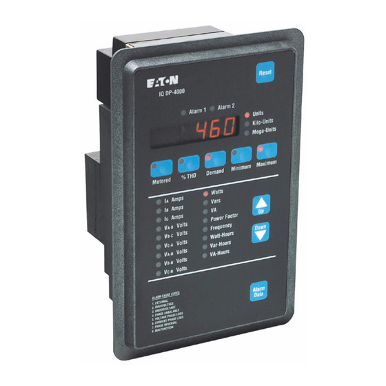
Product Overview and Features
Describes the IQ DP-4000, its models, and measured parameters.
Required User-Supplied Hardware
Details essential external hardware for operation.
Upgrading from IQ Data Plus II
Information on replacing older IQ Data Plus II units.
Replacement Parts and Accessories
Lists available parts and accessories for ordering.
Hardware Description
Introduction to Hardware Components
Overview of the IQ DP-4000's hardware components.
Operator Panel Description
Details the functions of the front panel interface.
Rear Access Area and Connections
Describes the rear connections and access points.
User-Supplied External Hardware
Lists external components required for installation.
Optional Communications Modules
Information on add-on modules for networking.
Specifications
General Specifications
Overall environmental and power requirements.
Protective Function Specifications
Details on voltage/current loss, unbalance, and reversal protection.
Metering Specifications
Specifies accuracy for amperes, voltage, watts, vars, etc.
Operator Panel
Introduction and Pushbuttons
Overview of the front panel and its controls.
Display Window and LEDs
Explanation of the display window and indicator LEDs.
Installation and Startup
Introduction and Panel Preparation
Outlines installation and panel mounting procedures.
Mounting Power Supply Module Separately
Instructions for mounting the power supply module remotely.
Wiring Procedures
Guidelines for connecting the IQ DP-4000 wiring.
Wiring Diagrams Overview
Illustrates various wiring configurations for the device.
Initial Startup Procedure
Steps for initial power application and verification.
Programming the IQ DP-4000
Introduction to Programming Setpoints
Explains how setpoints are programmed using switches and rotary select.
Setting Setpoint Switches
Step-by-step instructions for setting programming switches.
System Configuration Setpoints
Configures system parameters like voltage, frequency, and phase.
Demand and Energy Setpoints
Configures demand calculation and energy measurement settings.
Var/Power Factor and Alarm Functions
Sets display conventions and introduces alarm features.
Alarm Setpoint Configuration
Enables and configures specific alarm conditions and modes.
Alarm Detection and Reset Levels
Sets thresholds for alarm activation and reset.
PowerNet and Optional I/O Setpoints
Configures remote access and external input/output functions.
Troubleshooting and Maintenance
Level of Repair and Maintenance
Defines scope for unit-level troubleshooting and product upkeep.
Troubleshooting Overview
Introduces troubleshooting by initial startup and operation.
Replacement Procedure
Step-by-step instructions for replacing the unit.
Technical Assistance
Contact information for technical support.
Initial Power-On Troubleshooting
Common issues and solutions during initial startup.
Operational Troubleshooting Guide
Identifies symptoms, causes, and solutions for operational issues.
Return Procedure
Instructions for returning the unit for repair or replacement.
Appendix A: PT Ratio and CT Primary Setpoint Values
Setpoint Switch Configuration Reference
Tables detailing switch settings for various PT/CT ratios.
Appendix B: Setpoint Record Sheets
Master Setpoint Record Sheet
Template for recording all setpoint switch configurations.
General System Setpoint Record Sheet
Forms for recording General System setpoint configurations.
Alarm 1 Setpoint Record Sheet
Forms for recording Alarm 1 setpoint configurations.
Alarm 2 Setpoint Record Sheet
Forms for recording Alarm 2 setpoint configurations.
Optional I/O Setpoint Record Sheet
Forms for recording Optional I/O setpoint configurations.
Table of Contents
Save PDF
Print
Rename the bookmark
Delete bookmark?
Delete from my manuals?
Login
Sign In
OR
Sign in with Facebook
Sign in with Google
Upload manual
Upload from disk
Upload from URL
Need help?
Do you have a question about the IQDP4030 and is the answer not in the manual?
Questions and answers