
Subscribe to Our Youtube Channel
Related Manuals for Eaton XV400


Summary of Contents for Eaton XV400
- Page 1 12/2010 MN04802009Z-EN Operating Instructions replaces M000746-07, 03/2010 XV400 5.7"/8.4" MICRO PANEL...
- Page 2 None of this document may be reproduced or processed, duplicated or distributed by electronic systems in any form (print, photocopy, microfilm or any other process) without the written permission of Eaton Automation AG, St. Gallen. Subject to modifications. MICRO PANEL XV400 5.7"/8.4" 12/2010 MN04802009Z-EN www.eaton.com...
-
Page 3: Table Of Contents
Engineering conditions of acceptability by Underwriters Labaratories Inc. (UL) ..5.2.2 Requirements for the mounting position ..............Cable preparation......................5.3.1 Overview of interfaces....................5.3.2 Preparation of cables with D-Sub connector............... 5.3.3 Power supply....................... 5.3.4 RS232 (System Port) ....................5.3.5 Ethernet........................MICRO PANEL XV400 5.7"/8.4" 12/2010 MN04802009Z-EN www.eaton.com... - Page 4 5.7" devices XV-450-57 and XV-460-57 ..............9.2.3 8.4" devices......................... Touch sensor ......................9.3.1 Devices with resistive touch ..................9.3.2 Devices with infra-red touch..................System ........................Interfaces ........................9.5.1 Power supply....................... Enclosure ratings ......................MICRO PANEL XV400 5.7"/8.4" 12/2010 MN04802009Z-EN www.eaton.com...
- Page 5 Contents Agency approvals and standards................Applicable standards and regulations ................. Ambient conditions...................... MICRO PANEL XV400 5.7"/8.4" 12/2010 MN04802009Z-EN www.eaton.com...
- Page 6 Contents MICRO PANEL XV400 5.7"/8.4" 12/2010 MN04802009Z-EN www.eaton.com...
-
Page 7: General
Purpose of these Operating Instructions These Operating Instructions contain the information required for the correct and safe use of the MICRO PANELs XV400 5.7"/8.4"; MC2 5.7". The Operating Instructions are part of the devices and must therefore be kept nearby. - Page 8 1 General 1.3 Additional documentation MICRO PANEL XV400 5.7"/8.4" 12/2010 MN04802009Z-EN www.eaton.com...
-
Page 9: Device Description
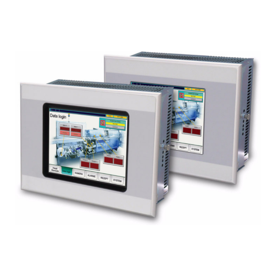
Device names XV400 5.7"/8.4" and MC2 5.7" are two different names of equivalent products. Function MICRO PANELs XV400 5.7"/8.4"; MC2 5.7" can be used as HMI devices or as integrated HMI/PLC devices. Intended use MICRO PANELs XV400 5.7"/8.4"; MC2 5.7" are primarily used in machine and system building. They are designed exclusively for the visualization, operation and control of machines and systems. - Page 10 Fig. 2 5.7" device with infra-red touch and standard front Fig. 3 5.7" device with infra-red touch and 4-hole front Fig. 4 5.7" device with infra-red touch and stainless steel front Fig. 5 8.4" device MICRO PANEL XV400 5.7"/8.4" 12/2010 MN04802009Z-EN www.eaton.com...
-
Page 11: Package Contents
2 Device description 2.5 Package contents Package contents The accessories supplied with the MICRO PANELs XV400 5.7"/8.4"; MC2 5.7" depend on the device version. 2.5.1 Package contents for devices with resistive touch and standard front Designation MICRO PANEL: XV-432-57CQB-1-1x or ... -
Page 12: Package Contents For Devices With 4-Hole Front
- Mounting with increased protection class: See Chapter 9.6 Enclosure ratings, 74. - Use in a potentially explosive atmosphere: See Chapter 9.7 Agency approvals and standards, 74. Required communication module MICRO PANEL XV400 5.7"/8.4" 12/2010 MN04802009Z-EN www.eaton.com... -
Page 13: Designation
Permissible mounting options (top edge «Top») Support To ensure fast and optimum support always provide the support personnel with the following informa- tion on the nameplate: Part no. (Part-No or Art.-No) Serial no. MICRO PANEL XV400 5.7"/8.4" 12/2010 MN04802009Z-EN www.eaton.com... - Page 14 2 Device description 2.7 Designation MICRO PANEL XV400 5.7"/8.4" 12/2010 MN04802009Z-EN www.eaton.com...
-
Page 15: Safety Regulations
Read this chapter before working with the device. This contains important information for your personal safety. This chapter must be read and understood by all persons work- ing with this device. MICRO PANEL XV400 5.7"/8.4" 12/2010 MN04802009Z-EN www.eaton.com... -
Page 16: Meaning Of Symbols
Signal word CAUTION without safety alert symbol Indicates a situation which, if not avoided, could result in material damage. Indicates useful information. The danger symbol used and the text indicate the actual danger and the related preventative measures. MICRO PANEL XV400 5.7"/8.4" 12/2010 MN04802009Z-EN www.eaton.com... -
Page 17: Mandatory Requirements, Personnel
It must be ensured that the device is properly connected, mounted, maintained and disposed of in compliance with all relevant standards and safety regulations. 3.3.5 Prohibited use The implementation of safety functions (relating to the protection of personnel and machinery) using the device is prohibited. MICRO PANEL XV400 5.7"/8.4" 12/2010 MN04802009Z-EN www.eaton.com... -
Page 18: Requirements For Proper Operation
Failure or malfunction of the device Improper handling or use Failure to observe the Operating Instructions Conversions, modifications and repairs to the device Repairs, see Chapter 7.3.1 Repairs, 61. MICRO PANEL XV400 5.7"/8.4" 12/2010 MN04802009Z-EN www.eaton.com... -
Page 19: Device Related Hazards
Avoid contact with components (such as connector pins) that are susceptible to electrostatic discharge. Discharge (by touching a grounded metal object) any static charge accumulated in your body before touching the device. MICRO PANEL XV400 5.7"/8.4" 12/2010 MN04802009Z-EN www.eaton.com... - Page 20 Do not use any pointed or sharp objects (e.g. knife) for cleaning. Do not use any aggressive or abrasive cleaning agent or solvent. Avoid any liquid entering the device (risk of short-circuit). MICRO PANEL XV400 5.7"/8.4" 12/2010 MN04802009Z-EN www.eaton.com...
-
Page 21: Operating And Indication Elements
(min. ø 7 mm). It is not necessary to touch the infra-red touch protective panel. B Display Display operating and indication elements. Tab. 6 Operating and indication elements on the front MICRO PANEL XV400 5.7"/8.4" 12/2010 MN04802009Z-EN www.eaton.com... -
Page 22: Operating Elements On The Service Side
Slot for CF card with operating system and normally with PLC and visu- alization projects. C Ejector button Ejecting the CF card. D Control button Function depends on the software used. Tab. 7 Operating elements on the service side MICRO PANEL XV400 5.7"/8.4" 12/2010 MN04802009Z-EN www.eaton.com... -
Page 23: Indication Elements On The Service Side
Flashes if the resistive touch is incorrectly calibrated (touch calibra- tion, → Document «MN05010007Z-EN System Description Windows CE»). E SUPPLY OK (green) Lit if all internal system voltages are present. Tab. 8 Indication elements on the service side MICRO PANEL XV400 5.7"/8.4" 12/2010 MN04802009Z-EN www.eaton.com... - Page 24 4 Operating and indication elements 4.3 Indication elements on the service side MICRO PANEL XV400 5.7"/8.4" 12/2010 MN04802009Z-EN www.eaton.com...
-
Page 25: Installation
5 Installation 5.1 Safety regulations Installation Safety regulations Read Chapter 3 Safety regulations, 15 before installing and commissioning the de- vice. This contains important information for your personal safety. MICRO PANEL XV400 5.7"/8.4" 12/2010 MN04802009Z-EN www.eaton.com... -
Page 26: Requirements For The Place Of Installation
Material thickness at the mounting cutout 2…5 mm (devices with 4-hole front: 2…20 mm) Flatness ≤ 0.5 mm (this requirement must also be fulfilled when the device is mounted!) Surface roughness Rz ≤ 120 MICRO PANEL XV400 5.7"/8.4" 12/2010 MN04802009Z-EN www.eaton.com... - Page 27 Special specifications apply to the mounting surfaces of devices with a stainless steel front which have to ensure protection to IP69K (required for cleaning with high-pressure cleaners), see Chapter 5.4.5 Mounting a device with stainless steel front (mounting to IP69K), 49. MICRO PANEL XV400 5.7"/8.4" 12/2010 MN04802009Z-EN www.eaton.com...
-
Page 28: Cable Preparation
The cables used must be prepared according to the interface description in this document. The wiring instructions for the relevant interface must be observed when wiring the device. Any generally applicable regulations and standards must be fulfilled. MICRO PANEL XV400 5.7"/8.4" 12/2010 MN04802009Z-EN www.eaton.com... -
Page 29: Overview Of Interfaces
D System Port → Chapter 5.3.4, 33 E Power supply → Chapter 5.3.3, 32 F DIAG Only for service tasks G USB Device → Chapter 5.3.6, 35 Tab. 9 Overview of interfaces MICRO PANEL XV400 5.7"/8.4" 12/2010 MN04802009Z-EN www.eaton.com... -
Page 30: Preparation Of Cables With D-Sub Connector
The folded back shield braid end must be covered by the heat shrinkable tubing or by the rubber grommet. Fit the D-Sub connector to the cable end: The exposed metal shield braid must be clamped to the connector casing with the cable clamp. MICRO PANEL XV400 5.7"/8.4" 12/2010 MN04802009Z-EN www.eaton.com... - Page 31 E D-Sub connector C Cable clamp F Mounting screw UNC The EMC values stated in the technical data (immunity and emission) can only be guar- anteed by observing the prescribed cable preparation! MICRO PANEL XV400 5.7"/8.4" 12/2010 MN04802009Z-EN www.eaton.com...
-
Page 32: Power Supply
Pluggable screw terminal Cross-section min. 0.75 mm / max. 2.5 mm (lead or wire) min. AWG18 / max. AWG12 Stripping length 7 mm Tab. 11 Preparing the wiring of the connector MICRO PANEL XV400 5.7"/8.4" 12/2010 MN04802009Z-EN www.eaton.com... -
Page 33: Rs232 (System Port)
Tab. 13 Relationship of cable length / baud rate When preparing the cables, ensure that there is a low-resistance connection between the cable shield and the connector casing (→ Chapter 5.3.2, 30). MICRO PANEL XV400 5.7"/8.4" 12/2010 MN04802009Z-EN www.eaton.com... -
Page 34: Ethernet
Communication can be disturbed and the connection mechanics damaged if the Ethernet interface is exposed to severe vibration or the RJ45 plug connection is pulled. Protect the RJ45 connection from severe vibration. Protect the RJ45 connection from pulling on the socket. MICRO PANEL XV400 5.7"/8.4" 12/2010 MN04802009Z-EN www.eaton.com... -
Page 35: Usb Device
5.3.7 USB Host The USB Host interface supports USB 2.0. Fig. 19 USB Host interface (USB Host, type A) Cable Only use shielded USB standard cable. Maximum cable length: 5 m. MICRO PANEL XV400 5.7"/8.4" 12/2010 MN04802009Z-EN www.eaton.com... -
Page 36: Can
Capacitance per unit length < 60 pF/m ≥ 0.25 mm Core cross-section / max. cable length / 100 m ≥ 0.34 mm / 250 m ≥ 0.75 mm / 500 m Tab. 16 Cable specifications MICRO PANEL XV400 5.7"/8.4" 12/2010 MN04802009Z-EN www.eaton.com... - Page 37 No more than two terminations must be provided on each bus segment. Transmission faults can occur if operation is carried out without the correct termina- tion. Fig. 21 Bus segment with four bus stations MICRO PANEL XV400 5.7"/8.4" 12/2010 MN04802009Z-EN www.eaton.com...
-
Page 38: Mounting
The device is not provided with an On/Off switch. If the power supply is not provided with a switch, the device will start up (boot) as soon as it is connected to the power sup- ply. MICRO PANEL XV400 5.7"/8.4" 12/2010 MN04802009Z-EN www.eaton.com... -
Page 39: Fitting The Communication Module In The Device
Avoid contact with components (such as connector pins) that are susceptible to electrostatic discharge. Discharge (by touching a grounded metal object) any static charge accumulated in your body before touching the device. MICRO PANEL XV400 5.7"/8.4" 12/2010 MN04802009Z-EN www.eaton.com... - Page 40 Fit the communication module in the slot. Fasten the communication module with the two knurled screws. Refer to the relevant module description for information on protocol, configuration, cable lengths etc. of the communication module to be used. MICRO PANEL XV400 5.7"/8.4" 12/2010 MN04802009Z-EN www.eaton.com...
-
Page 41: Mounting A Device With Standard Front
The join of the sealing strip must be positioned on the bottom of the device. Do not twist the sealing strip when it is inserted. Cut the sealing strip to a suitable length so that the join is tight. MICRO PANEL XV400 5.7"/8.4" 12/2010 MN04802009Z-EN www.eaton.com... - Page 42 Tightening the threaded pins too tightly may damage the device. Tighten threaded pins with a max. tightening torque of 0.2 Nm. The positions of the retaining brackets depend on the mounting requirements. MICRO PANEL XV400 5.7"/8.4" 12/2010 MN04802009Z-EN www.eaton.com...
- Page 43 One retaining bracket at each of the fixing positions (left, right and in the center) Left and right on the device: One retaining bracket each at the central fixing position Fig. 28 Devices with eight retaining brackets (meet IP65 requirements) MICRO PANEL XV400 5.7"/8.4" 12/2010 MN04802009Z-EN www.eaton.com...
-
Page 44: Mounting A Device With 4-Hole Front
B Countersunk screw Fit the countersunk screws in the corresponding holes of the device front plate. Place the device face down with the countersunk screws. Pull off the protective foil from the supplied front seal. MICRO PANEL XV400 5.7"/8.4" 12/2010 MN04802009Z-EN www.eaton.com... - Page 45 Use the supplied countersunk screws and optional counter frame if: Mounting is required to comply with IP65, or The device is used in a potentially explosive atmosphere. Fig. 31 Counter frame (for mounting to IP65) MICRO PANEL XV400 5.7"/8.4" 12/2010 MN04802009Z-EN www.eaton.com...
-
Page 46: Mounting A Device With Stainless Steel Front (Standard Mounting And Mounting To Ip65)
Fig. 32 Mounting cutout for 5.7" devices Fit the supplied seal: Fig. 33 Seal CAUTION Poor sealing Poor sealing resulting from the twisting of the seal or due to protruding securing tabs. Insert the seal correctly. MICRO PANEL XV400 5.7"/8.4" 12/2010 MN04802009Z-EN www.eaton.com... - Page 47 Tightening the threaded pins too tightly may damage the device. Tighten threaded pins with a tightening torque of 0.25…0.3 Nm. The positions of the retaining brackets depend on the mounting requirements. MICRO PANEL XV400 5.7"/8.4" 12/2010 MN04802009Z-EN www.eaton.com...
- Page 48 One retaining bracket at each of the fixing positions (left, right and in the center) Left and right on the device: One retaining bracket each at the central fixing position Fig. 37 Devices with eight retaining brackets (meet IP65 requirements) MICRO PANEL XV400 5.7"/8.4" 12/2010 MN04802009Z-EN www.eaton.com...
-
Page 49: Mounting A Device With Stainless Steel Front (Mounting To Ip69K)
After mounting suitable measures must be taken to achieve the required sealing in accordance with IP69K. 198.0 +1/-1 6…9 212.5 +0.3/-0.3 Fig. 38 Mounting cutout for 5.7" devices Fit the supplied seal: Fig. 39 Seal MICRO PANEL XV400 5.7"/8.4" 12/2010 MN04802009Z-EN www.eaton.com... - Page 50 Tighten threaded pins with a tightening torque of 0.25…0.3 Nm. Top and bottom of the device: One retaining bracket at each of the fixing positions (left, right and in the center) MICRO PANEL XV400 5.7"/8.4" 12/2010 MN04802009Z-EN www.eaton.com...
- Page 51 In the following figure the device front plate is not mounted in the mounting plate. IP69K is not ensured. A suitable protection must be fitted. Fig. 44 Device front plate is not flush mounted MICRO PANEL XV400 5.7"/8.4" 12/2010 MN04802009Z-EN www.eaton.com...
- Page 52 5 Installation 5.4 Mounting MICRO PANEL XV400 5.7"/8.4" 12/2010 MN04802009Z-EN www.eaton.com...
-
Page 53: Operation
If condensation is present on the device, or if it was exposed to temperature fluc- tuations, it must be allowed to adjust to room temperature (do not expose the de- vice to the direct heat of heating devices) prior to commissioning. MICRO PANEL XV400 5.7"/8.4" 12/2010 MN04802009Z-EN www.eaton.com... -
Page 54: Starting The Device
Do not apply any force (CF cards are protected against reverse insertion). Fig. 46 Service side of the device (CF slot cover removed) Fit the CF slot cover (A). Energize the device. The device will boot. MICRO PANEL XV400 5.7"/8.4" 12/2010 MN04802009Z-EN www.eaton.com... - Page 55 System Description Windows CE»): Adjust the system settings of the device. Install the required application programs. The lifespan of the backlight can be increased by reducing the brightness (→ Document «MN05010007Z-EN System Description Windows CE»). MICRO PANEL XV400 5.7"/8.4" 12/2010 MN04802009Z-EN www.eaton.com...
-
Page 56: Switching Off The Device
(CCFL) of the backlight. Avoid frequent on/off switching of the device. Reduce the brightness of the backlight instead (→ Document «MN05010007Z-EN System Description Windows CE»). De-energize the device. MICRO PANEL XV400 5.7"/8.4" 12/2010 MN04802009Z-EN www.eaton.com... -
Page 57: Maintenance And Service
7 Maintenance and service 7.1 Safety regulations Maintenance and service Safety regulations Read Chapter 3 Safety regulations, 15 before working with the device. This contains important information for your personal safety. MICRO PANEL XV400 5.7"/8.4" 12/2010 MN04802009Z-EN www.eaton.com... -
Page 58: Maintenance
Recalibrating a resistive touch The resistive touch is already calibrated when delivered. However, it must be recalibrated if it does not respond correctly to touch operation. Touch calibration, see Document «MN05010007Z-EN System Description Windows CE». MICRO PANEL XV400 5.7"/8.4" 12/2010 MN04802009Z-EN www.eaton.com... -
Page 59: Cleaning The Infra-Red Touch
In practice, the specifications of the high-pressure cleaners have higher tolerances. We therefore urgently recommend that the following information is added to the cleaning in- structions for XV400 5.7"/8.4"; MC2 5.7" with stainless steel front. Information in cleaning instructions: Property... -
Page 60: Recalibrating The Infra-Red Touch
Tab. 19 Information in cleaning instructions 7.2.4 Recalibrating the infra-red touch Devices with infra-red touch do not have to be recalibrated. 7.2.5 Battery The integrated battery cannot be exchanged. Lifespan, see Chapter 9.4 System, 72. MICRO PANEL XV400 5.7"/8.4" 12/2010 MN04802009Z-EN www.eaton.com... -
Page 61: Service
Repairs The device must only be opened by the manufacturer or by an authorized repair center. Contact your local supplier or Eaton technical support for repairs. Only the original packaging should be used for transporting the device. MICRO PANEL XV400 5.7"/8.4" 12/2010 MN04802009Z-EN www.eaton.com... -
Page 62: Troubleshooting
Start (boot) the device. Calibrate touch (→ Document «MN05010007Z-EN System Description Windows CE»). Infra-red frame of the infra-red touch is contam- Clean the infra-red frame inated. (→ Chapter 7.2.3, 59). MICRO PANEL XV400 5.7"/8.4" 12/2010 MN04802009Z-EN www.eaton.com... - Page 63 The threaded pins for mounting the device have Loosen the threaded pins (observe max. torque, → Chapter 5.4, 38). been tightened too much. Device is faulty. Send in your device for repair. Tab. 20 Troubleshooting MICRO PANEL XV400 5.7"/8.4" 12/2010 MN04802009Z-EN www.eaton.com...
- Page 64 7 Maintenance and service 7.4 Troubleshooting MICRO PANEL XV400 5.7"/8.4" 12/2010 MN04802009Z-EN www.eaton.com...
-
Page 65: Storage, Transport And Disposal
Damage to the device must be prevented during transport (use an appropriate packaging). The ambient conditions must be fulfilled even when the device is transported. See Chapter 9.9 Ambient conditions, 76. Check the device on arrival for damage in transit. MICRO PANEL XV400 5.7"/8.4" 12/2010 MN04802009Z-EN www.eaton.com... -
Page 66: Disposal
Tab. 21 Materials used in the device Materials used in the packaging Packaging Material External packaging Cardboard Internal packaging Closed-cell polyethylene foam, CFC-free Plastic bag: Polyethylene (PE) Tab. 22 Materials used in the packaging MICRO PANEL XV400 5.7"/8.4" 12/2010 MN04802009Z-EN www.eaton.com... -
Page 67: Technical Data
198 mm × 142 mm (±1 mm) Weight Devices with standard front Approx. 1.9 kg Devices with stainless steel front Approx. 2.3 kg Tab. 23 Dimensions and weights of the 5.7" devices with standard or stainless steel front MICRO PANEL XV400 5.7"/8.4" 12/2010 MN04802009Z-EN www.eaton.com... -
Page 68: Devices With 4-Hole Front
Thickness of front plate 5 mm Mounting depth 76 mm Mounting cutout 198 mm × 142 mm (±1 mm) Weight Approx. 1.9 kg Tab. 24 Dimensions and weights of the 5.7" devices with 4-hole front MICRO PANEL XV400 5.7"/8.4" 12/2010 MN04802009Z-EN www.eaton.com... -
Page 69: Devices
95 mm Thickness of front plate 5 mm Mounting depth 90 mm Mounting cutout 261 mm × 194 mm (±1 mm) Weight Approx. 3.0 kg Tab. 25 Dimensions and weights of the 8.4" devices MICRO PANEL XV400 5.7"/8.4" 12/2010 MN04802009Z-EN www.eaton.com... -
Page 70: Display
LED, dimmable via software Lifespan Normally 40 000 h Resistive touch back panel Touch sensor (absolutely flat, seamless) Infra-red touch protective panel Non-reflective safety glass Tab. 27 Display of the 5.7" devices XV-450-57 and XV-460-57 MICRO PANEL XV400 5.7"/8.4" 12/2010 MN04802009Z-EN www.eaton.com... -
Page 71: Devices
Property XV400 5.7"/8.4"; MC2 5.7" Type Infra-red touch Resolution 5.7" devices 47 × 31 logic channels 8.4" devices 63 × 47 logic channels Tab. 30 Touch sensor of the devices with infra-red touch MICRO PANEL XV400 5.7"/8.4" 12/2010 MN04802009Z-EN www.eaton.com... -
Page 72: System
USB 2.0 (1.5 / 12 Mbit/s), not electrically isolated USB Device USB 1.1, not electrically isolated CAN, electrically isolated Power supply → Chapter 9.5.1, 73 DIAG Only for service tasks Tab. 32 Interfaces MICRO PANEL XV400 5.7"/8.4" 12/2010 MN04802009Z-EN www.eaton.com... -
Page 73: Power Supply
Max. 1.1 A (24 VDC) Starting current inrush 2.5 A Protection against reverse polarity Fuse Yes (replacement only by the manufacturer or by an authorized repair center) Potential isolation Tab. 33 Power supply MICRO PANEL XV400 5.7"/8.4" 12/2010 MN04802009Z-EN www.eaton.com... -
Page 74: Enclosure Ratings
Required accessories for mounting: - For devices with standard front: Additional set of retaining brackets (optional) - For devices with 4-hole front: Counter frame (optional) UL 60950: File no. E208621 Tab. 35 Agency approvals and standards MICRO PANEL XV400 5.7"/8.4" 12/2010 MN04802009Z-EN www.eaton.com... -
Page 75: Applicable Standards And Regulations
(Engineering conditions of acceptability by UL, → Chapter 5.2.1, 26) Product standards EN 50178 Electronic equipment for use in power installations EN 61131-2 Programmable logic controllers, equipment require- ments and tests Tab. 36 Applicable standards and regulations MICRO PANEL XV400 5.7"/8.4" 12/2010 MN04802009Z-EN www.eaton.com... -
Page 76: Ambient Conditions
0 … 50°C Storage / Transport -20 … 60°C Relative air humidity 10 … 95%, non-condensing Vibration According to IEC68-2-6 Shock According to IEC68-2-27 Fall test According to IEC68-2-32 Tab. 37 Ambient conditions MICRO PANEL XV400 5.7"/8.4" 12/2010 MN04802009Z-EN www.eaton.com...
Need help?
Do you have a question about the XV400 and is the answer not in the manual?
Questions and answers