Advertisement
Quick Links
Advertisement

Subscribe to Our Youtube Channel
Related Manuals for Eaton PDI WaveStar


Summary of Contents for Eaton PDI WaveStar
- Page 1 Eaton® PDI WaveStar Color Monitor Setup and Operation Manual p/n: P-164001109 Revision 01...
- Page 2 ToughRail Technology, and WaveStar are registered trademarks of Power Distribution Inc. All other trademarks are held by their respective owners. All other trademarks are property of their respective companies. ©Copyright 2023 Eaton, Raleigh, NC, USA. All rights reserved. No part of this document may be reproduced in any way without the express written approval of Eaton.
- Page 3 Dear Customer, On behalf of everyone at Eaton, we thank you for partnering with us, and trusting us to maintain your business continuity and preventing downtime at your facility. Our suite of backup power, power distribution and power management products are designed to protect you from a host of threats including power outages, surges, lighting strikes, and enable you to monitor and control your power infrastructure.
- Page 5 5 5 D D e e v v i i c c e e C C h h a a i i n n : : S S e e t t t t i i n n g g s s ....................................................2 2 1 1 5.1 Initial Device Chain............................ 21 5.2 Device Settings............................22 Eaton PDI WaveStar Color Monitor Setup and Operation Manual P-164001109—Rev 01...
- Page 6 1 1 1 1 A A p p p p e e n n d d i i x x : : C C o o l l o o r r M M o o n n i i t t o o r r B B a a c c k k p p a a n n e e l l ............................................5 5 5 5 Eaton PDI WaveStar Color Monitor Setup and Operation Manual P-164001109—Rev 01...
- Page 7 Figure 36. Web Pages: Display Device ......................47 Figure 37. Web Pages: PDU Board......................... 48 Figure 38. Web Pages: Enhanced Subfeeds ..................... 49 Figure 39. Color Monitor Backpanel........................ 55 Eaton PDI WaveStar Color Monitor Setup and Operation Manual P-164001109—Rev 01...
- Page 8 List of Figures viii Eaton PDI WaveStar Color Monitor Setup and Operation Manual P-164001109—Rev 01...
- Page 9 Table 6. Contractor Board Alarms ......................... 42 Table 7. Circuit Alarms ..........................42 Table 8. Panelboard Alarms......................... 43 Table 9. CB Status Board Alarms........................43 Table 10. Troubleshooting Guide........................43 Eaton PDI WaveStar Color Monitor Setup and Operation Manual P-164001109—Rev 01...
- Page 10 List of Tables Eaton PDI WaveStar Color Monitor Setup and Operation Manual P-164001109—Rev 01...
- Page 11 Following these safety instructions is extremely important to avoid possible injury or death. The WaveStar ® Color Monitor must be installed by licensed electricians or by Eaton-authorized technicians. Follow safe electrical work practices: • Read, understand, and follow the instructions before installing this product.
- Page 12 Safety Eaton PDI WaveStar Color Monitor Setup and Operation Manual P-164001109—Rev 01...
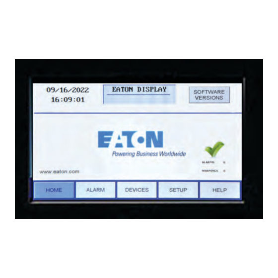
- Page 13 ® Color Monitor is a 7-inch color touchscreen which displays power management information for up to twenty (20) Branch Circuit Monitoring System (BCMS) devices and other Eaton devices in the Monitor’s downstream Modbus network. The Color Monitor is incorporated into Eaton products, such as Power Distribution Units (PDUs), Remote Power Panels (RPPs), or JCOMM ®...
- Page 14 Power monitoring information as it is stored in each device’s points list (or Modbus register map) is in each DEVICE READINGS screen. Alarms and warnings are displayed on these screens: • ALARM: List of all extant warnings and alarms by device name Eaton PDI WaveStar Color Monitor Setup and Operation Manual P-164001109—Rev 01...
- Page 15 Canada: 1-800-461-9166 ext 260 All other countries: Call your local service representative Please use the following e-mail for manual comments, suggestions, or to report a technical error in this manual. Eaton PDI WaveStar Color Monitor Setup and Operation Manual P-164001109—Rev 01...
- Page 16 2 2 . . 6 6 W W a a r r r r a a n n t t y y To view the warranty please click on the link or copy the address to download from the Eaton website: Eaton Product Warranty https://www.eaton.com/content/dam/eaton/products/backup-power-ups-surge-it-power-distribution/backup-...
- Page 17 The Color Monitor’s backpanel has Modbus RTU and Ethernet ports (see Figure For Color Monitors embedded in Eaton products (PDUs, RPPs, or JCOMMs), Modbus RTU backpanel connections are typically made in manufacturing and extended to a terminal block or external panel for convenient customer access.
- Page 18 3 3 . . 2 2 . . 2 2 M M o o d d b b u u s s R R T T U U 2 2 - - W W i i r r e e v v s s . . 4 4 - - W W i i r r e e C C o o n n f f i i g g u u r r a a t t i i o o n n Eaton devices have two (2) jumpers near their Modbus ports for configuring 2-wire vs. 4-wire Modbus RTU...
- Page 19 3 3 . . 3 3 . . 2 2 C C a a b b l l e e B B i i a a s s i i n n g g a a n n d d T T e e r r m m i i n n a a t t i i o o n n Eaton devices have soft biasing (27K pull-up and pull-down resistors) on the + and – transmit and receive lines.
- Page 20 C C u u s s t t o o m m e e r r M M o o d d b b u u s s R R T T U U C C o o n n n n e e c c t t i i o o n n s s When a Color Monitor is embedded in a Eaton product (PDU, RPP, or JCOMM), the customer does not typically wire Modbus RTU directly to the Monitor.
- Page 21 Downstream connections CUSTOMER are internal to the RPP CONNECTION and are wired at the LAB08314 factory. Internal Label shows Modbus RTU wiring. Eaton PDI WaveStar Color Monitor Setup and Operation Manual P-164001109—Rev 01...
- Page 22 Connections Panel on the left inside of the unit. Figure 9. JCOMM Modbus Connections Modbus Out Connector Common Common Modbus Plug Modbus Plug Wiring 4-Wire Wiring 2-Wire with 2-Wire Jumpers Modbus In Connector JCOMM Connections Panel Eaton PDI WaveStar Color Monitor Setup and Operation Manual P-164001109—Rev 01...
- Page 23 Upstream Modbus on the Color Monitor supports three (3) Modbus commands only (with typical flag and data values shown in hexadecimal) for communicating with the points lists of the Monitor or devices in its chain: Read Server ID (command 11) Eaton PDI WaveStar Color Monitor Setup and Operation Manual P-164001109—Rev 01...
- Page 24 The following commands are supported and are typical for the product: • snmpget • snmpgetnext • snmpset See the MIB file for specifics. The MIB can be downloaded from the Eaton website. Reference the Bibliography in this manual. Eaton PDI WaveStar Color Monitor Setup and Operation Manual P-164001109—Rev 01...
- Page 25 “Eaton DISPLAY”) is on same screen as Modbus setup. TIME & DATE: Set time and date; used on HOME screen and alarm timestamps. CALIBRATE GUI: See next figure. See 4.2 Network Setup Eaton PDI WaveStar Color Monitor Setup and Operation Manual P-164001109—Rev 01...
- Page 26 Screen, where the added devices will initially show up as generic device names. • For each new device the user should then enter a unique device name. Unique device names are needed to isolate alarms and measurements to specific devices. Eaton PDI WaveStar Color Monitor Setup and Operation Manual P-164001109—Rev 01...
- Page 27 The following must be specified for Modbus TCP/IP: • IP Address • Subnet Mask • Gateway Each connected monitor must be assigned a unique address. DHCP is not supported. Eaton PDI WaveStar Color Monitor Setup and Operation Manual P-164001109—Rev 01...
- Page 28 Set Community security string for Set operations. Touch RESTART WITH NEW SETTINGS if any parameter is changed on this screen. The processor will reboot and search the network for connections. Eaton PDI WaveStar Color Monitor Setup and Operation Manual P-164001109—Rev 01...
- Page 29 Display Version Number is given by the Monitor’s onboard software. • Device Version Numbers are entered in device setup: Go to DEVICES screen, select device, select VERSION field, and enter data. Eaton PDI WaveStar Color Monitor Setup and Operation Manual P-164001109—Rev 01...
- Page 30 Setup: Monitor and Network Eaton PDI WaveStar Color Monitor Setup and Operation Manual P-164001109—Rev 01...
- Page 31 BCMS KWH (BCMS KWH panelboard points list), which provides power usage measurements for individual panelboard circuits BCMS CB, a small points list, associated with BCMS Normal or KWH points lists, with current measurements for two subfeeds from a PDU or RPP. Eaton PDI WaveStar Color Monitor Setup and Operation Manual P-164001109—Rev 01...
- Page 32 Touch VERSION field. • A keyboard appears. • If requested, enter version number update password (“VNUP”) + touch ENTER. • Enter Version number for PDU board + touch ENTER. Eaton PDI WaveStar Color Monitor Setup and Operation Manual P-164001109—Rev 01...
- Page 33 Standard panelboards are always laid out 1, 3, 5… 41 down the left side and 2, 4, 6… 42 down the right side. Select ODD/EVEN to display them in this order or select STANDARD to display them as consecutive numbers (1, 2, 3... 42) down left then down right side. Eaton PDI WaveStar Color Monitor Setup and Operation Manual P-164001109—Rev 01...
- Page 34 Normal and BCMS KWH points lists, but when used is a separate list with its own Modbus address.) Each BCMS device gets its own device entry in the Monitor’s device chain, its own points list, and its own Modbus address. Eaton PDI WaveStar Color Monitor Setup and Operation Manual P-164001109—Rev 01...
- Page 35 Set version: Touch VERSION box to enter software versions. Keyboard appears requesting password and then requests that you enter the version code (enter “VNUP”). Eaton PDI WaveStar Color Monitor Setup and Operation Manual P-164001109—Rev 01...
- Page 36 Set version: Touch VERSION box to enter software versions. Keyboard appears requesting password and then requests that you enter the version code (enter “VNUP”). Eaton PDI WaveStar Color Monitor Setup and Operation Manual P-164001109—Rev 01...
- Page 37 P P D D U U D D e e v v i i c c e e R R e e a a d d i i n n g g s s READINGS from the PDU are power measurements at input to and output from the PDU transformer (see Figure 22). Eaton PDI WaveStar Color Monitor Setup and Operation Manual P-164001109—Rev 01...
- Page 38 PDU circuits that are subfeeds to other PDUs or RPPs (see and ). Enhanced Subfeeds devices can monitor • Up to (14) 3-phase circuits (ABC) • Up to (10) 3-phase plus neutral circuits (ABCN) Eaton PDI WaveStar Color Monitor Setup and Operation Manual P-164001109—Rev 01...
- Page 39 If neutrals are also monitored: • Only 10 circuits total can be monitored with this ESF device. • There is an extra line for each neutral circuit (shown at left). Eaton PDI WaveStar Color Monitor Setup and Operation Manual P-164001109—Rev 01...
- Page 40 BCMS Normal points list allows customization of thresholds and alarm level for each individual circuit, which is done in BCMS setup, not in the Color Monitor. KWH Power measurements are available only for panelboard totals. See , "Readings: BCMS Normal". Eaton PDI WaveStar Color Monitor Setup and Operation Manual P-164001109—Rev 01...
- Page 41 Line 2 = voltage source 2, if present Panelboard power measurements by phases ABC and total: KVAR Panelboard cumulative reading: KWH panelboard total Clear = Reset KWH to 0. Eaton PDI WaveStar Color Monitor Setup and Operation Manual P-164001109—Rev 01...
- Page 42 0 after having read a minimum current WARNING: OK = No warning outstanding; ACTIVE = warning outstanding ALARM: OK = No alarm outstanding; ACTIVE = Alarm is outstanding Eaton PDI WaveStar Color Monitor Setup and Operation Manual P-164001109—Rev 01...
- Page 43 Enhanced Subfeeds (ESF) points list. A BCMS Data Acquisition PCB can have three Modbus addresses: two panelboards with BCMS Normal or KWH points list and a third BCMS CB subfeeds points list. Eaton PDI WaveStar Color Monitor Setup and Operation Manual P-164001109—Rev 01...
- Page 44 1L1 to 1L72. Panelboard circuits are numbered sequentially down the left side (1L1-1L36) and then down the right side (1L37-1L72). BCMS IEC points list does not have the BCMS CB subfeeds option. Eaton PDI WaveStar Color Monitor Setup and Operation Manual P-164001109—Rev 01...
- Page 45 Harmonic Distortion %) by phase: Voltage source Frequency Panelboard totals instantaneous power measurements by phases ABC and total: KVAR Panelboard cumulative reading: KWH to panelboard as whole Clear = Reset KWH to 0. Eaton PDI WaveStar Color Monitor Setup and Operation Manual P-164001109—Rev 01...
- Page 46 Circuit Breaker Status Modbus points list Open or Closed Tripped/Not Tripped or SNMP MIB. Contacts not listed as “Active” in the Modbus points list or MIB are not shown. Eaton PDI WaveStar Color Monitor Setup and Operation Manual P-164001109—Rev 01...
- Page 47 In the device list, scroll to the device name that has the warning/alarm. Touch the device name to show the device’s circuit list. Step through the device’s screen chain with PREVIOUS/NEXT to find the ALARM heading. Eaton PDI WaveStar Color Monitor Setup and Operation Manual P-164001109—Rev 01...
- Page 48 KWH points list). problem to the main voltage Device Name should be changed from source to the panelboard. generic name to user-specified name on the device’s SETTINGS screen. Eaton PDI WaveStar Color Monitor Setup and Operation Manual P-164001109—Rev 01...
- Page 49 Table 2. Monitor Alarms Alarm Alarm Description DISPLAY Comm. N Error (N is device Communication error with one of the devices in the Monitor’s downstream device number from 1-20): chain Eaton PDI WaveStar Color Monitor Setup and Operation Manual P-164001109—Rev 01...
- Page 50 Input current phase A measures above threshold level (optional). Input Current A Low Input current phase A measures below threshold level (optional). Input Current B High Input current phase B measures above threshold level (optional). Eaton PDI WaveStar Color Monitor Setup and Operation Manual P-164001109—Rev 01...
- Page 51 Output KW phase C measures above preset level. Output KW Total High Output KW total measures above threshold level in points list. Output KVA A High Output KVA phase A measures above preset level. Eaton PDI WaveStar Color Monitor Setup and Operation Manual P-164001109—Rev 01...
- Page 52 CB N High Current Warning (N = 1-336) Circuit N exceeds high current warning threshold. CB N High Current Alarm (N = 1-336) Circuit N exceeds high current alarm threshold. Eaton PDI WaveStar Color Monitor Setup and Operation Manual P-164001109—Rev 01...
- Page 53 Go to the Setup screen and press RESTART WITH NEW SETTINGS to force the display to search for downstream devices. Eaton PDI WaveStar Color Monitor Setup and Operation Manual P-164001109—Rev 01...
- Page 54 The downstream device’s options are not Check the downstream device’s setup. setup properly or the downstream device is reading an analog value that is outside of its expected range. Eaton PDI WaveStar Color Monitor Setup and Operation Manual P-164001109—Rev 01...
- Page 55 A “device” is a points list or Modbus register map that corresponds to a physical device, such as a panelboard. The following web pages show a PDU with an M4G acquisition board (M4GACK), subfeeds monitored through the BCMS Enhanced Subfeeds points list, and a Color Monitor. Eaton PDI WaveStar Color Monitor Setup and Operation Manual P-164001109—Rev 01...
- Page 56 35) is the Color Monitor itself, whose web page only shows the number of devices in the Monitor’s device chain, firmware level, and a user-defined model ID (see Figure 36). Eaton PDI WaveStar Color Monitor Setup and Operation Manual P-164001109—Rev 01...
- Page 57 Click the PDU device line brings up the PDU M4G acquisition board web page (M4GACK) (see Figure 37). Click Device 3 BCMS ESF in the Web Pages Device Chain (see Figure 38) to see monitoring data for the PDU’s subfeeds to its downstream devices. Eaton PDI WaveStar Color Monitor Setup and Operation Manual P-164001109—Rev 01...
- Page 58 Web Pages Figure 37. Web Pages: PDU Board Eaton PDI WaveStar Color Monitor Setup and Operation Manual P-164001109—Rev 01...
- Page 59 Web Pages Figure 38. Web Pages: Enhanced Subfeeds Eaton PDI WaveStar Color Monitor Setup and Operation Manual P-164001109—Rev 01...
- Page 60 Web Pages Eaton PDI WaveStar Color Monitor Setup and Operation Manual P-164001109—Rev 01...
- Page 61 Modbus RTU Modbus protocol send over TCP/IP, which provides higher transmission speeds. Modbus TCP/IP Modbus register map. Points List Power Distribution Unit. Remote Power Panel. Simple Network Management Protocol. SNMP Eaton PDI WaveStar Color Monitor Setup and Operation Manual P-164001109—Rev 01...
- Page 62 Glossary Eaton PDI WaveStar Color Monitor Setup and Operation Manual P-164001109—Rev 01...
- Page 63 \SNMP Product MIB Files. The MIB for a Color Monitor with PDUs or RPPs is in Wavestar Color Monitor PDU-RPP and is named "PDI-FDI-DISPLAY-14-a.mib". Eaton manufactures a variety of power distribution products. Product documentation can be downloaded from Eaton website: https://www.eaton.com/us/en-us/products/backup-power-ups-surge-it-power-distribution/power-distribution-...
- Page 64 Bibliography Eaton PDI WaveStar Color Monitor Setup and Operation Manual P-164001109—Rev 01...
- Page 65 0.5A at 120VAC or 30VDC. The backpanel also has a RESET button: If the Monitor hangs, you can reset it by pressing this button. Figure 39. Color Monitor Backpanel Eaton PDI WaveStar Color Monitor Setup and Operation Manual P-164001109—Rev 01...
- Page 66 BSG (CR2477), 3V, 1 AH (PDI Part Number 15174) only. Use of another battery may present a risk of fire or explosion. Dispose of used battery promptly. Keep away from children. Do not disassemble and do not depose of in fire. Eaton PDI WaveStar Color Monitor Setup and Operation Manual P-164001109—Rev 01...
- Page 67 Appendix: Color Monitor Backpanel Eaton PDI WaveStar Color Monitor Setup and Operation Manual P-164001109—Rev 01...
- Page 68 P-16400110901 P-164001109 01...
Need help?
Do you have a question about the PDI WaveStar and is the answer not in the manual?
Questions and answers