Sign In
Upload
Download
Table of Contents
Contents
Add to my manuals
Delete from my manuals
Share
URL of this page:
HTML Link:
Bookmark this page
Add
Manual will be automatically added to "My Manuals"
Print this page
×
Bookmark added
×
Added to my manuals
Manuals
Brands
Fukuda Denshi Manuals
Medical Equipment
FX-7102
Service manual
Fukuda Denshi FX-7102 Service Manual
Hide thumbs
Also See for FX-7102
:
Operation manual
(20 pages)
1
2
3
4
5
6
Table Of Contents
7
8
9
10
11
12
13
14
15
16
17
18
19
20
21
22
23
24
25
26
27
28
29
30
31
32
33
34
35
36
37
38
39
40
41
42
43
44
45
46
47
48
49
50
51
52
53
54
55
56
57
58
59
60
61
62
63
64
65
66
67
68
69
70
71
72
73
74
75
76
77
78
79
80
81
82
83
84
85
86
87
88
89
90
91
92
93
94
95
96
97
98
99
100
101
102
103
104
105
106
107
108
109
110
111
112
113
114
115
116
117
118
119
120
121
122
123
124
125
126
127
128
129
130
131
132
133
134
135
136
137
138
139
140
141
142
143
144
145
146
147
148
149
150
151
152
153
154
155
156
157
158
159
160
161
162
163
164
165
166
167
168
169
170
page
of
170
Go
/
170
Contents
Table of Contents
Troubleshooting
Bookmarks
Table of Contents
Table of Contents
Unit (Top Face)
Unit (Side, Rear, and Bottom Faces)
Operation Panel
Specifications List
Chapter 1 Component Names and Functions ·······························································1-1
Chapter 2 Troubleshooting
On Power Supply in Equipment (ECG AMP Not Included)
On ECG AMP Supply Voltage
Problem Conditions and Corrective Action
Unit Doesn't Start up When Main Power Is Switched on
Battery Operations Are Not Executed
Troubleshooting Related to Supply Voltages
Failures Related to Charging Operations
Charge Error LED Is Lit
Charging Operation Ended Normally, but the Battery Is Nearly Uncharged
LCD Does Not Display or Display Is Abnormal
Cannot Perform Key Operations
Date/Time Changes
Buzzer Would Not Sound
Recording Paper Is Fed, but Printing and Waveform Recording Are Not Performed
Recording Paper Is Not Fed
A Certain Lead Record Appears as a Baseline
All 12-Lead Patient Records Appear as Baselines
Detection of Electrode Misposition Cannot be Led
Some Leads Do Not Detect Electrode Misposition
Chapter 3 Maintenance
Cleaning
Cleaning the Unit
Replacing the Battery
Update of the Software
Self-Diagnostics Test
User Self-Diagnostics Test
ECG Test Pattern
Recording Test
Key Test
LCD Test
Buzzer Test
Manufacturer Self-Diagnostics Test
Status Test
Ecg A/D Data
LAN Test
Memory Test
ROM WRITE Test
Recorder Test
Memory Initialize
Update
Periodical Inspections
Periodical Inspection Intervals and Precautions
List of Periodical Inspection Items
Safety Inspections (4 Items)
Before Checking the Leakage Current
Checking the Enclosure Leakage Current
Checking the Patient Leakage Current III
Checking the Patient Measurement Current
Checking the Enclosure Leakage Current (Current that Flows from the Enclosure to the Earth Terminal of the Power Outlet)
Checking the Patient Leakage Current I
Inspection of Electrical Performance/Characteristics
Hardware Inspections (10 Items)
Periodical Inspection(2) Record
Chapter 4 Disassembly
Removing the LCD
Removing the Enclosure Cover
Removing the Recorder Unit
Removing the Main Board
Chapter 5 Electric Circuit Diagrams ···············································································5-1
Overall Block Diagram of Unit (AC Adapter Not Included)
Electric Circuit Diagrams
Overall Block Diagram of Unit (AC Adaptor Not Included)
MAIN BOARD Block Diagram
MAIN BOARD (PCB-6950) Circuit
Digital Logic Block
CPU Section
FPGA Section
Memory Section
KEY I/F Section
Thermal Head Control Section
Real Time Clock
Reset Circuit Section
Sensor Control Section
Motor Control Section
LCD Voltage Generating Section
ECG AMP Block
Power Supply Block
Power Voltage Generating Section
Battery Charging Section
Power Control Section
KEY BOARD (PCB-6949) Circuit
SENSOR BOARD (PCB-6948) Circuit
MAG up BOARD (PCB-6951) Circuit
AC Adaptor Block Diagram
MAIN BOARD Circuit Diagrams (PCB-6950)
Power Connection Table
Power Connection Table No.1
Power Connection Table No.2
CPU Block
FPGA Block
MEMORY Block
LAN CONTROL Block
LCD I/F / RTC / LED Block
THERMAL I/F Block
SENSOR I/F /MAGAZIN up SENSOR I/FMOTOR I/F /JTAG I/F Block
ECG AMP Block (ADC,CPLD and POWER Section)
MAIN POWER SUPPLY +24V Block
CHARGE Block
3.3V /+1.8V Power Generation Block
POWER STATUS Block
POWER / CHARGE ERROR Block
VSTB / POWER on RESET Block
Battery on Control/ Thermal Powergeneration Block
POWER-MAIN I/F Block
POWER ON/OFF CONTROL Block
Key Board (Pcb-6949)
Sensor Board (Pcb-6948)
Mag up Board (Pcb-6951)
Chapter 6 Spare Parts List ······························································································6-1
Main Board (Pcb-6950)
Sensor Board (Pcb-6948)
Mag up Board (Pcb-6951)
Chapter 7 Board Component Diagram ···········································································7-1
MAIN BOARD (PCB-6950 Soldering Side)
KEY BOARD (PCB-6949 Component Side)
KEY BOARD (PCB-6949 Soldering Side)
SENSOR BOARD (PCB-6948 Component Side)
MAG up BOARD (PCB-6951 Component Side)
Chapter 8 Assembly Diagrams
Magazine
Paper Shaft
Recorder
Upper Case (FX-7102)
Upper Case (FCP-7101)
Lower Case
General Assembly Diagram (FX-7102)
General Assembly Diagram (FCP-7101)
Outline View (FX-7102)
Outline View (FCP-7101)
Paper Guide
50Mm Magazine Adapter (Option)
50Mm Paper Adapter (Option)
Chapter 9 Technical Instructions Related to EMC
Immunity Information (to Other than Radiation/Conduction)
Immunity Information (to Radiation/Conduction)
Recommended Distance of Separation from Portable Telephone, Etc
Advertisement
Quick Links
1
Table of Contents
2
Operation Panel
3
Recording Paper Is Fed, but Printing and Waveform Recording Are Not Performed
Download this manual
F
C
P
F
C
P
・ Before setting up/maintenance, please read this service manual carefully.
・ Keep this manual where it can be always referred to.
-
7
1
0
1
-
7
1
0
1
●
Service Manual
●
/
F
X
-
7
/
F
X
-
7
S T
R A
N T
C O
1
0
2
1
0
2
Table of
Contents
Previous
Page
Next
Page
1
2
3
4
5
Advertisement
Table of Contents
Troubleshooting
Troubleshooting
19
Troubleshooting related to supply voltages
25
Need help?
Do you have a question about the FX-7102 and is the answer not in the manual?
Ask a question
Questions and answers
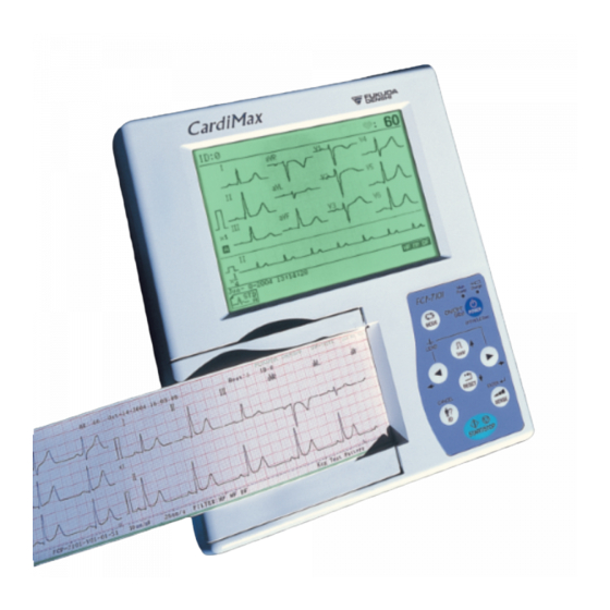
Related Manuals for Fukuda Denshi FX-7102
Medical Equipment Fukuda Denshi CARDIMAX FX-7102 Operation Manual
Electrocardiograph (20 pages)
Medical Equipment Fukuda Denshi CARDIMAX FX-7202 Operation Manual
Electrocardiograph (204 pages)
Medical Equipment Fukuda Denshi FX-7202 Service Manual
(160 pages)
Medical Equipment Fukuda Denshi FX-2111 Service Manual
Electrocardiograph (128 pages)
Medical Equipment Fukuda Denshi FX-2111 Service Manual
Electrocardiograph (128 pages)
Medical Equipment Fukuda Denshi FX-2111 Service Manual
Electrocardiograph (128 pages)
Medical Equipment Fukuda Denshi CardiMax FX-8322 Service Manual
General purpose ecg (142 pages)
Medical Equipment Fukuda Denshi FX-7302 Service Manual
Electrocargiograph (162 pages)
Medical Equipment Fukuda Denshi FX-8400 Connection Manual
(7 pages)
Medical Equipment Fukuda Denshi CardiMax8 Operation Manual
Electrocardiograph (388 pages)
Medical Equipment Fukuda Denshi FX-7542 Service Manual
Electrocardiograph (202 pages)
Medical Equipment Fukuda Denshi FCP-7101 Service Manual
(170 pages)
Medical Equipment Fukuda Denshi FCP-2155 Service Manual
Interpretive electrocardiograph (136 pages)
Medical Equipment Fukuda Denshi LX-8000 Series Operation Manual
Ecg, respiration and spo2 transmitter (110 pages)
Medical Equipment Fukuda Denshi HJ-500 Service Manual
(202 pages)
Medical Equipment Fukuda Denshi HBX-800 Service Manual
Bisx i/f unit (22 pages)
Summarization of Contents
Safety and Notices
Safety Information
Explains graphic symbols for safe operation of the equipment.
Servicing Precautions
Guidelines for safe and correct servicing procedures for the FCP-7101/FX-7102.
Equipment Classification
Classification of the unit based on safety and operational standards.
Component Names and Functions
Unit Component Overview
Identifies components on the top, side, rear, and bottom surfaces of the unit.
Operation Panel Functions
Details the controls and indicators on the unit's operation panel.
Technical Specifications
Lists technical specifications for the FCP-7101/FX-7102 electrocardiograph.
Troubleshooting Procedures
Power Supply and Startup Issues
Diagnosing power, voltage, and unit startup problems.
Battery and Charging Problems
Troubleshooting battery operation and charging failures.
Display, Keypad, and Buzzer Malfunctions
Resolving issues with the LCD, control keys, and buzzer.
Recording and Paper Feed Errors
Troubleshooting paper detection and feeding problems.
ECG Signal and Lead Interpretation Issues
Diagnosing baseline and electrode misposition problems.
Maintenance Procedures
Unit Cleaning and Battery Replacement
Procedures for cleaning the unit and replacing the internal battery.
Software Updates and Diagnostics
Instructions for software updates and an overview of self-diagnostics.
Periodical Inspection Guidelines
Schedule and procedures for regular maintenance inspections.
Disassembly Procedures
Removing the LCD
Step-by-step instructions for removing the LCD module.
Removing the Enclosure Cover
Detailed steps for safely removing the unit's outer casing.
Removing the Recorder Unit
Instructions for removing the paper recorder mechanism.
Removing the Main Board
Procedure for safely removing the main circuit board.
Electric Circuit Diagrams
Overall Unit Block Diagram
High-level overview of the unit's main functional blocks.
Main Board Circuit Details
Illustrates the main board's structure and major circuit blocks.
Key Component Schematics
Schematics for major functional blocks like CPU, FPGA, Memory, ECG AMP, Power Supply.
Interface Board Schematics
Schematics for interface boards (Key, Sensor, LAN).
Parts and Assembly Information
Spare Parts Lists
Comprehensive listing of all available spare parts for the unit.
Board Component Layouts
Diagrams showing component placement on main, key, and sensor boards.
Unit Assembly Diagrams
Exploded views and part lists for major unit assemblies.
EMC Compliance Information
Emission and Immunity Declarations
Information on electromagnetic emission and immunity compliance.
RF Interference Separation Guidelines
Guidelines for minimum separation distances from RF transmitters.
Table of Contents
Save PDF
Print
Rename the bookmark
Delete bookmark?
Delete from my manuals?
Login
Sign In
OR
Sign in with Facebook
Sign in with Google
Upload manual
Upload from disk
Upload from URL
Need help?
Do you have a question about the FX-7102 and is the answer not in the manual?
Questions and answers