Sign In
Upload
Manuals
Brands
Fukuda Denshi Manuals
Medical Equipment
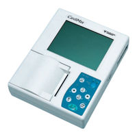
FX-7102
Fukuda Denshi FX-7102 Manuals
Manuals and User Guides for Fukuda Denshi FX-7102. We have
2
Fukuda Denshi FX-7102 manuals available for free PDF download: Service Manual, Operation Manual
Fukuda Denshi FX-7102 Service Manual (170 pages)
Brand:
Fukuda Denshi
| Category:
Medical Equipment
| Size: 6 MB
Table of Contents
Table of Contents
7
Unit (Top Face)
13
Unit (Side, Rear, and Bottom Faces)
14
Operation Panel
15
Specifications List
17
Chapter 1 Component Names and Functions ·······························································1-1
19
Chapter 2 Troubleshooting
19
On Power Supply in Equipment (ECG AMP Not Included)
21
On ECG AMP Supply Voltage
22
Problem Conditions and Corrective Action
23
Unit Doesn't Start up When Main Power Is Switched on
24
Battery Operations Are Not Executed
24
Troubleshooting Related to Supply Voltages
25
Failures Related to Charging Operations
26
Charge Error LED Is Lit
26
Charging Operation Ended Normally, but the Battery Is Nearly Uncharged
26
LCD Does Not Display or Display Is Abnormal
27
Cannot Perform Key Operations
28
Date/Time Changes
29
Buzzer Would Not Sound
29
Recording Paper Is Fed, but Printing and Waveform Recording Are Not Performed
30
Recording Paper Is Not Fed
30
A Certain Lead Record Appears as a Baseline
30
All 12-Lead Patient Records Appear as Baselines
31
Detection of Electrode Misposition Cannot be Led
31
Some Leads Do Not Detect Electrode Misposition
31
Chapter 3 Maintenance
33
Cleaning
35
Cleaning the Unit
35
Replacing the Battery
36
Update of the Software
38
Self-Diagnostics Test
39
User Self-Diagnostics Test
40
ECG Test Pattern
41
Recording Test
42
Key Test
43
LCD Test
44
Buzzer Test
45
Manufacturer Self-Diagnostics Test
46
Status Test
48
Ecg A/D Data
49
LAN Test
50
Memory Test
51
ROM WRITE Test
52
Recorder Test
53
Memory Initialize
55
Update
56
Periodical Inspections
57
Periodical Inspection Intervals and Precautions
57
List of Periodical Inspection Items
57
Safety Inspections (4 Items)
58
Before Checking the Leakage Current
58
Checking the Enclosure Leakage Current
59
Checking the Patient Leakage Current III
59
Checking the Patient Measurement Current
59
Checking the Enclosure Leakage Current (Current that Flows from the Enclosure to the Earth Terminal of the Power Outlet)
59
Checking the Patient Leakage Current I
59
Inspection of Electrical Performance/Characteristics
60
Hardware Inspections (10 Items)
62
Periodical Inspection(2) Record
64
Chapter 4 Disassembly
67
Removing the LCD
69
Removing the Enclosure Cover
70
Removing the Recorder Unit
71
Removing the Main Board
72
Chapter 5 Electric Circuit Diagrams ···············································································5-1
75
Overall Block Diagram of Unit (AC Adapter Not Included)
75
Electric Circuit Diagrams
75
Overall Block Diagram of Unit (AC Adaptor Not Included)
75
MAIN BOARD Block Diagram
77
MAIN BOARD (PCB-6950) Circuit
79
Digital Logic Block
79
CPU Section
79
FPGA Section
79
Memory Section
80
KEY I/F Section
82
Thermal Head Control Section
83
Real Time Clock
84
Reset Circuit Section
85
Sensor Control Section
86
Motor Control Section
87
LCD Voltage Generating Section
88
ECG AMP Block
89
Power Supply Block
90
Power Voltage Generating Section
91
Battery Charging Section
94
Power Control Section
95
KEY BOARD (PCB-6949) Circuit
96
SENSOR BOARD (PCB-6948) Circuit
97
MAG up BOARD (PCB-6951) Circuit
97
AC Adaptor Block Diagram
98
MAIN BOARD Circuit Diagrams (PCB-6950)
99
Power Connection Table
99
Power Connection Table No.1
99
Power Connection Table No.2
99
CPU Block
102
FPGA Block
103
MEMORY Block
104
LAN CONTROL Block
105
LCD I/F / RTC / LED Block
106
THERMAL I/F Block
107
SENSOR I/F /MAGAZIN up SENSOR I/FMOTOR I/F /JTAG I/F Block
108
ECG AMP Block (ADC,CPLD and POWER Section)
110
MAIN POWER SUPPLY +24V Block
111
CHARGE Block
112
3.3V /+1.8V Power Generation Block
113
POWER STATUS Block
114
POWER / CHARGE ERROR Block
115
VSTB / POWER on RESET Block
116
Battery on Control/ Thermal Powergeneration Block
117
POWER-MAIN I/F Block
118
POWER ON/OFF CONTROL Block
119
Key Board (Pcb-6949)
132
Sensor Board (Pcb-6948)
133
Mag up Board (Pcb-6951)
134
Chapter 6 Spare Parts List ······························································································6-1
137
Main Board (Pcb-6950)
137
Sensor Board (Pcb-6948)
137
Mag up Board (Pcb-6951)
137
Chapter 7 Board Component Diagram ···········································································7-1
140
MAIN BOARD (PCB-6950 Soldering Side)
140
KEY BOARD (PCB-6949 Component Side)
141
KEY BOARD (PCB-6949 Soldering Side)
142
SENSOR BOARD (PCB-6948 Component Side)
143
MAG up BOARD (PCB-6951 Component Side)
144
Chapter 8 Assembly Diagrams
145
Magazine
147
Paper Shaft
148
Recorder
149
Upper Case (FX-7102)
150
Upper Case (FCP-7101)
151
Lower Case
152
General Assembly Diagram (FX-7102)
153
General Assembly Diagram (FCP-7101)
154
Outline View (FX-7102)
155
Outline View (FCP-7101)
156
Paper Guide
157
50Mm Magazine Adapter (Option)
158
50Mm Paper Adapter (Option)
159
Chapter 9 Technical Instructions Related to EMC
161
Immunity Information (to Other than Radiation/Conduction)
165
Immunity Information (to Radiation/Conduction)
166
Recommended Distance of Separation from Portable Telephone, Etc
168
Advertisement
Fukuda Denshi FX-7102 Operation Manual (20 pages)
ELECTROCARDIOGRAPH
Brand:
Fukuda Denshi
| Category:
Medical Equipment
| Size: 0 MB
Advertisement
Related Products
Fukuda Denshi CARDIMAX FX-7202
Fukuda Denshi FX-7302
Fukuda Denshi FX-7542
Fukuda Denshi FX-2111
Fukuda Denshi FCP-7101
Fukuda Denshi CardiMax FX-8322
Fukuda Denshi CardiMax FX-8322R
Fukuda Denshi FCP-2155
Fukuda Denshi FX-9800
Fukuda Denshi FRD100
Fukuda Denshi Categories
Medical Equipment
Transmitter
Monitor
Measuring Instruments
Control Unit
More Fukuda Denshi Manuals
Login
Sign In
OR
Sign in with Facebook
Sign in with Google
Upload manual
Upload from disk
Upload from URL