Table of Contents
Advertisement
Quick Links
Advertisement
Table of Contents

Related Manuals for Seitron S4500


Summarization of Contents
1.0 IMPORTANT INFORMATION
1.1 Manual Information
Describes the manual's content, operation, and maintenance of the S1500/S4500 analyzer.
1.2 Danger Levels and Symbols
Explains hazard symbols and warnings for safe operation and environmental protection.
2.0 SAFETY
2.1 Intended Use
Details the application areas for the S1500/S4500 flue gas analyzer.
2.2 Improper Use
Clarifies prohibited uses and associated risks for the S1500/S4500.
3.0 WORKING PRINCIPLE
3.1 Principle of Operation
Explains the gas sampling, filtration, and analysis process within the instrument.
3.2 Measurement Sensors
Describes the types of electrochemical sensors used and their working mechanism.
4.0 PRODUCT DESCRIPTION
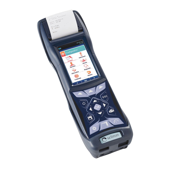
4.1 Analyzer Overview
Details the ergonomic design, keypad, and user-friendliness of the S1500/S4500.
4.2 Key Features
Highlights the analyzer's capabilities, including sensors, printer, and connectivity options.
4.3 Component Details
Provides an overview of the physical components of the flue gas analyzer.
4.3.1 Keypad and Display
Describes the user interface elements, including buttons and the TFT screen.
4.3.2 Printer and Connectors
Details the integrated printer and various input/output ports on the device.
6.0 TECHNICAL SPECIFICATIONS
6.1 General Specifications
Lists key technical data like autozero, dilution, sensors, and power.
6.2 Measurement and Accuracy Ranges
Presents detailed specifications for each measured parameter.
7.0 STARTUP AND CONNECTIONS
7.1 Preliminary Operations
Outlines essential steps before using the instrument, like checking contents and charging.
7.2 Analyzer Power Supply
Explains the Li-Ion battery, charging, and external power pack usage.
7.3 Connection Diagram
Illustrates how to connect various probes and accessories to the analyzer.
7.4 Gas Sampling Probe Setup
Details the connection and technical features of the gas sampling probe.
7.5 Combustion Air Temperature Probe
Describes the probe for measuring combustion air temperature for efficiency calculation.
8.0 POWER ON - OFF
8.1 Starting the Device
Guides on powering the instrument on and off, including error handling.
9.0 CONFIGURATION
9.1 Configuration Menu
Introduces the main menu structure for instrument settings and analysis parameters.
9.2 Analysis Settings
Explains how to configure parameters related to fuel type, condensation, and O2 reference.
9.3 Instrument Settings
Covers configuration for Bluetooth, time/date, brightness, pump, and sensors.
9.4 Operator Settings
Details how to set and manage operator profiles for analysis reports.
9.5 Alarm Settings
Explains how to configure alarm thresholds for various monitored parameters.
9.6 Diagnostic Settings
Guides on checking instrument status, sensor diagnostics, and pump checks.
10.0 MEMORY MANAGEMENT
10.1 Memory Menu
Introduces the functions for saving, recalling, and managing analysis data.
10.2 Saving Analyses
Describes the process of saving combustion analysis data manually or automatically.
10.3 Viewing Averages
Explains how to view and analyze averaged measurement data stored in memory.
10.4 Selecting and Recalling Memory
Guides on choosing memory slots and retrieving stored analysis data.
10.5 Deleting Memory
Details the procedure for removing individual or all stored analysis data.
11.0 PRINT FUNCTIONS
11.1 Print Menu
Introduces the printing options and report configuration for analysis results.
11.2 Report Settings
Explains how to configure the layout, copies, and content of printouts.
11.3 Print Configuration
Covers settings for copies, report models, and date/time inclusion in printouts.
11.4 Header Settings
Details how to customize header information for printed analysis reports.
11.5 Printer Pairing
Guides on connecting and pairing the instrument with a Bluetooth printer.
12.0 MEASUREMENTS
12.1 Measurement Overview
Introduces the various measurement types available on the analyzer.
12.2 Draft Measurement
Explains how to measure stack draft using the instrument's pressure sensor.
12.3 Smoke Measurement
Describes how to perform smoke spot number analysis using an optional kit.
12.4 Ambient CO Measurement
Details how to measure CO levels in the environment for safety checks.
12.5 Temperature Measurement
Explains how to measure supply and return water temperatures and their difference.
12.6 Pressure Measurement
Guides on measuring differential and external pressure using the instrument.
12.7 Velocity Measurement
Describes how to measure air or flue gas velocity using a Pitot tube.
12.8 Power of Burner Measurement
Explains how to calculate burner thermal power based on flow or meter readings.
13.0 FLUE GAS ANALYSIS
13.1 Analysis Procedure
Outlines the steps for performing a complete flue gas analysis.
13.2 Preliminary Operations
Details essential preparatory steps before starting flue gas analysis.
13.3 Manual Mode Analysis
Guides on conducting flue gas analysis manually, including data saving and printing.
13.4 Data Logger Mode Analysis
Explains how to set up and perform analysis using the data logger function.
14.0 SENSORS
14.1 Sensor Arrangement and Types
Shows sensor placement and lists available sensor models and their codes.
14.2 Gas Sensor Life
Provides information on the expected lifespan and recalibration requirements for sensors.
14.3 Sensor Expandability
Details how the instrument can be expanded to accommodate more sensors.
14.4 Specific Sensor Descriptions
Describes the CxHy sensor for unburnt hydrocarbons measurement.
14.5 CO2 Sensor Installation
Explains the mandatory autozero setting for the CO2 sensor.
14.6 Combustible Gas Leak Sensor
Describes the sensor for detecting gas leaks and its installation.
15.0 MAINTENANCE
15.1 Routine Maintenance
Provides general guidelines for regular upkeep of the instrument.
15.2 Preventive Maintenance
Recommends annual servicing by a qualified service center for optimal performance.
15.3 Cleaning Procedures
Details how to clean the sample probe and water trap/filter unit.
15.4 Component Replacements
Guides on replacing filters, sensors, battery pack, and printer paper.
15.5 Firmware Update
Explains the process for updating the instrument's firmware.
16.0 TROUBLESHOOTING
16.1 Troubleshooting Guide
Lists common issues and their probable causes and remedies for the analyzer.
17.0 SPARE PARTS AND SERVICING
17.1 Spare Parts
Lists available replacement parts for the instrument.
17.2 Accessories
Lists optional accessories that can be used with the analyzer.
17.3 Service Centers
Provides contact information for authorized service centers.
Need help?
Do you have a question about the S4500 and is the answer not in the manual?
Questions and answers