Table of Contents
Advertisement
Quick Links
Advertisement
Table of Contents

Related Manuals for Seitron S500


Summary of Contents for Seitron S500
-
Page 3: Table Of Contents
TABLE OF CONTENTS IMPORTANT INFORMATION Information about this manual Danger levels and other symbols SAFETY Safety check Intended purpose Improper use of the product Precautions for the usage of the Li-Ion battery package WORKING PRINCIPLE General overview of the analyzer DESCRIPTION OF THE PRODUCT Working principle Measurement cells... - Page 4 TABLE OF CONTENTS INSTRUMENT PARAMETER Setting Menu 10.0 MEASUREMENTS 10.1 Menu→Measurements 10.2 Menu→Measurements→Comb. analysis 10.3 Menu→Measurements→Draft 10.4 Menu→Measurements→CO air 10.5 Menu→Measurements→Pressure 11.0 MEMORY 11.1 Menu→Memory 12.0 CONFIGURATION 12.1 Menu→Configuration 12.2 Menu→Configurationan→Analysis 12.2.1 Menu→Configuration→Analysis→Fuel 12.2.2 Menu→Configuration→Analysis→Condensation 12.2.3 Menu→Configuration→Analysis→O2 Reference 12.2.4 Menu→Configuration→Analysis→Measure units 12.2.5 Menu→Configuration→Analysis→Autozero 12.2.6...
- Page 5 ANNEX D - Coefficients of the fuels and Formulas WARRANTY Seitron Americas Inc. - ALL RIGHTS RESERVED - Total or partial reproduction of this document by any means (including photocopying or storage on any electronic medium) and transmittal of same to third parties in any manner, even electronically, is strictly prohibited unless explicitly authorized in writing by Seitron Americas Inc.
-
Page 6: Important Information
1.1 Information about this manual This manual describes the operation and the characteristics and the maintenance of the Combustion Analyzer model S500. Read this operation and maintenance manual before using the device. The operator must be familiar with the manual and follow the instructions carefully. -
Page 7: Safety
This chapter describes the areas of application for which the S500 is intended. Using the S500 in other application areas is on the risk of the operator and the manufacturer assumes no responsibility and liability for loss, damage or costs which could be a result. It is mandatory to read and pay attention to the operating/maintenance manual. -
Page 8: Working Principle
- Generation and visualization of a QR code with the purpose of downloading the data of the acquired measures, having installed the App “SEITRON SMART ANALYSIS” which can be downloaded form the AppStore (if the version of the instrument foresees it). -
Page 9: Description Of The Product
Exhausted cells can be easily replaced by the user without depriving himself of the instrument and without complicated calibration procedures with certified mixtures as they are pre-calibrated before being supplied. Seitron americas certifies the accuracy of the measurements only upon a calibration certificate issued by its laboratory or other approved laboratory. -
Page 10: Bluetooth® Connection
4.9 IR connection The S500 analyzer is internally equipped with an infrared light interface which uses the HP-IR protocol, which allows the communication with a remote IR printer. 4.10 Software and available applications... -
Page 11: Components Description
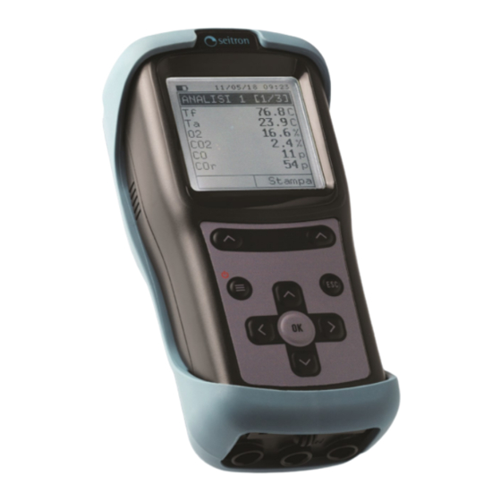
5.0 COMPONENTS DESCRIPTION 5.1 Instrument interface DESCRIPTION: Polyester keyboard with preformed keys and main command functions: KEYS FUNCTION Activates the context keys shown on the display. - Turns on and off the instrument. - If pressed briefly, accesses the instrument menu. - If pressed for at least 2 seconds, turns off the instrument. - Page 12 Display LCD backlit Display, White/Black 128 x 128 pixel with white LEDs. CAUTION: If the instrument is exposed to extremely high or extremely low temperatures, the quality of the display may be temporarily impaired. Display appearance may be improved by acting on the contrast key. Date, time and battery status.
-
Page 13: Technical Specifications
TECHNICAL SPECIFICATIONS 6.1 Technical specifications Power: Li-Ion battery pack with internal protection circuit. Average life of the battery package: 500 empty / full charge cycles. Battery charger: External 5Vdc 2A battery charger with female A-type USB connector + connection to the device with the same serial communication cable supplied. -
Page 14: Measurement And Accuracy Ranges
6.2 Measurement and Accuracy Ranges RESPONSE MEASUREMENT SENSOR RANGE RESOLUTION ACCURACY TIME T90 Electrochemical 0 .. 21.0% vol 0.1% vol ±0.2% vol <20 sec. sensor Electrochemical ±20 ppm 0 .. 400 ppm high H2 immunity 0 .. 4000 ppm 1 ppm <30 sec. -
Page 15: Using The Flue Gas Analyzer
Remove the instrument from its packing and check it for damage. Make sure that the content corresponds to the items ordered. If signs of tampering or damage are noticed, notify the Seitron Americas service center or agent immediately and keep the original packing. A label at the rear of the analyzer bears the serial number. This serial number should always be stated when requesting technical assistance, spare parts or clarification on the product or its use. -
Page 16: Use With External Power Pack
The instrument offers the possibility to generate and display a QR code with the purpose to download the data of the acquired measures, activating the interactive function “Print” visible on the display in the menu configuration, having installed the “Seitron Smart Analysis” downloadable from the AppStore. Minimum requirements for the App installation “Seitron Smart Analysis”... -
Page 17: Connection Diagram
7.5 Connection diagram AAKA01 AACTA03A AA SF7-A AAC KP02 K100000000S9 036103 130121... -
Page 18: Flue Gas Analysis
IF THE Tc-K CONNECTOR IS NOT PLUGGED IN, THE TEMPERATURE WILL NOT BE ACQUIRED. 11/12/17 10:00 11/12/17 10:00 AUTOZERO AUTOZERO Primary air acquisition T: 21.5°C S500-2 Keep N.S.:0 Primary air pressed for Fw:1.00-EVAL03 a few sec- acquisition keep Repeat onds... -
Page 19: Preliminary Operations
Keep When the autozero phase is complete, push the key related to the interactive function “ “, to pro- ceed with the combustion analysis or push the key related to the interactive function “ “, to repeat Repeat the autozero phase. 8.1.2 Preliminary Operations Following are reported the parameters to set before performing the combustion analysis:... -
Page 20: Performing The Combustion Analysis - Manual Mode
8.1.4 Performing the combustion analysis - Manual Mode 11/12/17 10:00 11/12/17 10:00 11/12/17 10:00 AN. SETTINGS ANALYSIS [1/3] PRINT ►Mode Manual 190.1 C Curr. analysis Fuel 15.4 C ►Copy number Natural gas 4.2 % Printer Start Print Memory 23 ppm QR Code Status Free... -
Page 21: 5Performing The Combustion Analysis - Auto Mode
15.4 C 91.4 % Print - SCAN THE QR CODE WITH THE SEITRON APP “CHEMIST QR CODE”, IN ORDER TO DOWNLOAD THE ACQUIRED DATA. THE VISUALIZED QR CODE IS REFERRING ONLY TO THE AVERAGE OF THE PERFORMED ANALYSIS. - IF IT IS NEEDED TO PRINT THE AVERAGE ANALYSES AND ADDITIONAL MEASURES →... - Page 22 Additional Information INTERACTIVE OPERATION DESCRIPTION By pushing the button related to this interactive function, the instrument stops the current analysis when the set time interval is over. This condition is shown with Pause the symbol “ “. Paused When the “Paused” phase is over, the interactive function “Keep” is shown. By Keep activating this function the acquired sample is memorized and the instrument continues with the acquisition of the next sample.
-
Page 23: End Of The Analysis
8.1.6 End of the Analysis - At the end of the combustion analysis, carefully remove the sample probe and remote air temperature probe, if used, from their relative ducts, taking care not to get burnt. - Switch off the instrument. Then, proceed to turn off the instrument. - Page 24 Cleaning hose Fig. b Maintaining the water trap / filter unit To remove the water trap, just rotate the cover and unhook the filter holder body; remove the internal cup and then replace the filter (see figure on the side). Clean all the filter parts using water only, dry the components and reassemble the filter.
-
Page 25: Instrument Parameter
INSTRUMENT PARAMETER 9.1 Menu 15/06/18 10:00 FUNCTION MENU Returns to the previous screen. ► Measurements Memory Configuration Selects the available parameters. Diagnostic Info service Enters in the selected parameter setting. SUB-MENU FUNCTION Through this menu, it is possible to execute the draft, ambient CO and pressure Measurements Measurements. -
Page 26: Measurements
10.0 MEASUREMENTS 10.1 Menu→Measurements 15/06/18 10:00 FUNCTION MEASUREMENTS Returns to the previous screen. ► Comb. analysis Draft CO air Selects the available parameters. Pressure Enters in the selected parameter setting. SUB MENU FUNCTION The user, with this menu, can set the different reference parameters of the instrument to Comb. -
Page 27: Menu→Measurements→Comb. Analysis
10.2 Menu→Measurements→Comb. analysis 11/12/17 10:00 FUNCTION SET ANALYSIS Activate the context keys shown on the ►Mode Auto display. Fuel Natural gas Returns to the previous screen. Interval Memory Status Free Selects the available parameters. Start Enters the selected parameter and con- firms the choice made. -
Page 28: Menu→Measurements→Draft
10.3 Menu→Measurements→Draft 15/06/18 10:00 FUNCTION DRAFT Activate the context keys shown on the Inlet display. Draft 0.00 h ►Zero sensor Returns to the previous screen. Starts the pressure sensor autozero. Save Print INTERACTIVE OPERATION FUNCTION Save The measure will be printed on the ticket of the current combustion analysis According to the version of the instrument and/or according with the related Print setting, it is possible to print or visualize the QR code... -
Page 29: Menu→Measurements→Co Air
10.4 Menu→Measurements→CO air 15/06/18 10:00 FUNCTION CO AIR Activate the context keys shown on the 412 p display. CO Max 413 p Returns to the previous screen. Save Print INTERACTIVE OPERATION FUNCTION Save The measure will be printed on the ticket of the current combustion analysis According to the version of the instrument and/or according with the related Print setting, it is possible to print or visualize the QR code... -
Page 30: Menu→Measurements→Pressure
10.5 Menu→Measurements→Pressure 15/06/18 10:00 FUNCTION PRESSURE Activate the context keys shown on the Press. 0.00 h display. ►Zero Sensor. Returns to the previous screen. Perform the Zero Sensor of the pres- sure sensor. Save Print INTERACTIVE OPERATION FUNCTION Save The measure will be printed on the ticket of the current combustion analysis According to the version of the instrument and/or according with the related Print setting, it is possible to print or visualize the QR code... -
Page 31: Memory
11.0 MEMORY 11.1 Menu→Memory FUNCTION 11/12/17 10:00 MEMORY Activate the context keys shown on the ► Memory display. Status full Modifies the memory number and then Time 09:50 confirms the changed setting. When selecting the analysis, shows the Date 11/12/17 detail of the evidenced analysis. - Page 32 2. Visualization of the memory content 11/12/17 10:00 11/12/17 10:00 11/12/17 10:00 AVERAGE [1/2] MEMORY MEMORY ► Average analysis 190.1 C ► Memory Analysis 1 15.4 C Status full Analysis 2 4.2 % Time 09:50 Select Analysis 3 23 ppm Date 11/12/17 Draft...
- Page 33 5. Detail of QR code generation to download the average analysis data and the additional measures. 11/12/17 10:00 11/12/17 10:00 PRINT MEMORY ► Average analysis Memory Analysis 1 ►Copy number Analysis 2 Printer Print Print Analysis 3 QR Code Draft Pairing BT Pressure Print...
-
Page 34: Configuration
12.0 CONFIGURATION 12.1 Menu→Configuration FUNCTION 11/12/17 10:00 CONFIGURATION Enters in the selected parameter. ► Analysis Instrument Alarm Selects the available parameters. Print Language Restore Returns to the previous screen. SUB MENU FUNCTION The user, through this menu, can set the different reference parameters of the instrument in order to perform the combustion analysis and/or additional Analysis measures. -
Page 35: Menu→Configurationan→Analysis
12.2 Menu→Configuration→Analysis 15/06/18 10:00 FUNCTION ANALYSIS Returns to the previous screen. ► Fuel Condensation reference Selects the available parameters. Measure units Autozero Air temp. Enters in the selected parameter. NOx/NO ratio SUB MENU FUNCTION Lets the user select the type of fuel to be used during analysis. Fuel SEE CHAPTER 12.2.1. -
Page 36: Menu→Configuration→Analysis→Fuel
12.2.1 Menu→Configuration→Analysis→Fuel 15/06/18 10:00 15/06/18 10:00 FUEL [1/2] FUEL [2/2] ► Natural gas Coal Propane ► Bio-fuel 5% #2 Oil Bagasse #4 Oil Butane #6 Oil Diesel Wood/Pel. 8% FUNCTION Returns to the previous screen. Scrolls through the pages. Confirms the choice of fuel to be used during the analysis. Example: 11/12/17 10:00... -
Page 37: Menu→Configuration→Analysis→Condensation
12.2.2 Menu→Configuration→Analysis→Condensation 15/06/18 10:00 CONDENSATION ► Altitude Altitude above sea level R.H. air Relative humidity of air FUNCTION When pressed in modify mode cancels the selection made, otherwise re- turns to the previous screen. The arrows select each line displayed. In edit mode, it scrolls through the suggested values. -
Page 38: Menu→Configuration→Analysis→O2 Reference
12.2.3 Menu→Configuration→Analysis→O2 Reference 15/06/18 10:00 02 REFERENCE ► CO 0.0 % Percentage of Oxygen in CO measurement 0.0 % Percentage of Oxygen in NO measurement FUNCTION When pressed in modify mode cancels the selection made, otherwise returns to the previous screen. The arrows select each line displayed. -
Page 39: Menu→Configuration→Analysis→Measure Units
12.2.4 Menu→Configuration→Analysis→Measure units 15/06/18 10:00 MEASURE UNITS ► CO Measurement unit can be set as: ppm - mg/m - mg/kWh - g/GJ - g/m ng/J - g/kWh - % Pressure Measurement unit can be set as: ppm - mg/m - mg/kWh - g/GJ - g/m ng/J - g/kWh - % Draft mmH2O... -
Page 40: Menu→Configuration→Analysis→Autozero
12.2.5 Menu→Configuration→Analysis→Autozero 15/06/18 10:00 AUTOZERO ► Autozero 30 s Duration of autozero, expressed in seconds. Purging Duration of the cleaning cycle, expressed in seconds. FUNCTION When pressed in modify mode cancels the selection made, otherwise re- turns to the previous screen. >... -
Page 41: Menu→Configuration→Analysis→Air Temp
12.2.6 Menu→Configuration→Analysis→Air temp 15/06/18 10:00 AIR TEMP. T probe --- F ►T air 32.0 F T probe FUNCTION Enters edit mode of the selected element and then confirms the change. > When in modify mode, sets the desired value. When pressed in modify mode cancels the selection made, otherwise re- turns to the previous screen. -
Page 42: Menu→Configuration→Analysis→Nox/No Ratio
12.2.7 Menu→Configuration→Analysis→NOx/NO Ratio (If NOx Sensor is installed) 15/06/18 10:00 NOx/NO RATIO ► NOx/NO 1.05 FUNCTION Enters edit mode of the selected element and then confirms the change. > When in modify mode, sets the desired value. When pressed in modify mode cancels the selection made, otherwise re- turns to the previous screen. -
Page 43: Menu→Configurationan→Instrument
12.3 Menu→Configuration→Instrument 15/06/18 10:00 FUNCTION INSTRUMENT Returns to the previous screen. ► Display On site calib. Clock Selects the available parameters. Bluetooth Enters in the selected parameter. SUB MENU FUNCTION With the arrow keys it is possible to increase or decrease the brightness and the Display contrast of the display. -
Page 44: Menu→Configuration→Instrument→Display
12.3.1 Menu→Configuration→Instrument→Display 15/06/18 10:00 DISPLAY ► Brightness Contrast FUNCTION When pressed in modify mode cancels the selection made, otherwise re- turns to the previous screen. The arrows select each line displayed. In edit mode, it scrolls through the suggested values. Enters the modify mode for the selected parameter, then confirms the modification. -
Page 45: Menu→Configuration→Instrument→On Site Calib
12.3.2 Menu→Configuration→Instrument→On site calib. 15/06/18 10:00 ON SITE CALIB. FUNCTION > Sets the password. Selects line; in modification sets the value or the desired mode. Once password is entered, gives access to the 'On site calibration' menu. Returns to the previous screen. When in modify mode cancels the modification just made. - Page 46 10:00 11/12/17 10:00 AUTOZERO AUTOZERO Primary air acquisition T: 21.5°C Keep pressed for S500-2 a few Primary air seconds N.S.:0 Fw:1.00-EVAL03 acquisition Keep Repeat WARNING Be sure that the autozero is performed in clean fresh air and that it terminates ...
- Page 47 3. The 'On site calibration' menu shows the list of the installed sensors for which the recalibration is available. In the recalibration screen all information related to the last performed calibration is shown, as well as the relevant values. Calibrate: saves new calibration 11/12/17 10:00...
- Page 48 OXIGEN SENSOR (O ) CALIBRATION DETAIL The calibration is possible only when the status is set to ‘----' (sensors that have never been calibrated before) otherwise it is necessary to set 'Status' to 'OFF' (see example below). 11/12/17 10:00 ON SITE CALIB.
- Page 49 When the stabilization time is over, select 'Calibration' and store the new calibration. 11/12/17 10:00 11/12/17 10:00 11/12/17 10:00 ON SITE CALIB. ON SITE CALIB. ON SITE CALIB. Calibration ► Calibration ► Calibration Status ---- Status ---- Status ► Durat. 00:05:28 Durat.
- Page 50 SENSOR CALIBRATION DETAIL FOR TOXIC GASES (EXAMPLE REFERRED TO CO). The calibration is possible only when the status is set to ‘----' (sensors that have never been calibrated before) otherwise it is necessary to set 'Status' to 'OFF' (see example below). 11/12/17 10:00 ON SITE CALIB.
- Page 51 The instrument measures the concentration of gas applied; wait at least 3 minutes to allow the reading to stabilize. The reading is shown in line 'Meas'. 11/12/17 10:00 11/12/17 10:00 ON SITE CALIB. ON SITE CALIB. Calibration Calibration Status ---- Status ----...
-
Page 52: Menu→Configuration→Instrument→Clock
12.3.3 Menu→Configuration→Instrument→Clock 15/06/18 10:00 CLOCK Time 9:00PM Time, in the chosen format Date 06/15/20 Date, in the chosen format Mode Date format: EU (Europe) or USA (America) Mode Time format: 24h or 12h FUNCTION When pressed in modify mode cancels the selection made, otherwise returns to the previous screen. -
Page 53: Menu→Configuration→Instrument→Bluetooth
12.3.4 Menu→Configuration→Instrument→Bluetooth (if available) 15/06/18 10:00 BLUETOOTH Status Bluetooth status: On or Off Device ID 008025CE0E6E Device MAC address FUNCTION Activate the context keys shown on the display. Goes back to the previous screen. INTERACTIVE OPERATIONS DESCRIPTION ® Turns off Bluetooth ®... -
Page 54: Menu→Configuration→Alarm
9.4.3 Menu→Configuration→Alarm 12.4 Menu→Configuration→Alarm 11/12/17 10:00 ALARM ► Measure Observed parameter: CO - NO - O2 Mode Kind of set alarm: Max / Min / Off Limit 18.0 % Concentration threshold of the observed gas. FUNCTION Enters the modify mode for the selected parameter, then confirms the modification. -
Page 55: Menu→Configuration→Print
QR code generation (if the instrument version foresees it): ON: pushing the button related to the interactive function “Print” the instrument generates a QR code, which can be read with the “Seitron Smart Analysis app” QR code and allows to download the data acquired of the performed combustion analysis and the additional measures. -
Page 56: Menu→Configuration→Print→Pairing
12.5.1 Menu→Configuration→Print→Pairing 1. When the Bluetooth printer is set, proceed with the following procedure: 15/06/18 10:00 15/06/18 10:00 15/06/18 10:00 PAIRING BT PAIRING BT PRINT Turn on the Printer Copy number detection in printer and Printer start searching progress ... Start QR code ►... -
Page 57: Menu→Configuration→Language
12.6 Menu→Configuration→Language 15/06/18 10:00 15/06/18 10:00 LANGUAGE [1/2] LANGUAGE [2/2] ► Italiano √ ► Polski English Pусский Español Français Hrvatski FUNCTION Returns to the previous screen. Scrolls through the available languages. Sets the selected language. Example: 15/06/18 10:00 15/06/18 10:00 LANGUAGE [1/2] LANGUAGE [1/2] ►... -
Page 58: Menu→Configuration→Reset
12.7 Menu→Configuration→Reset 15/06/18 10:00 15/06/18 10:00 RESET RESET Deleting and Clear memory data resetting data and restore factory setting? Push OK to continue FUNCTION Exits the current screen without resetting. Starts the factory data reset phase. K100000000S9 036103 130121... -
Page 59: Diagnostic
13.0 DIAGNOSTIC 13.1 Menu→Diagnostic FUNCTION 15/06/18 10:00 DIAGNOSTIC Returns to the previous screen. ► Sensors Gas probe Hardware Selects the available parameters. Enters in the selected parameter. SUB MENU DESCRIPTION Displays information on the state and calibration of the electrochemical sensors. Moreover, accesses to the ID data of the sensor: Code Sensors... -
Page 60: Menu→Diagnostic→Sensors
13.1.1 Menu→Diagnostic→Sensors Messages on the state and calibration of the electrochemical sensors: 15/06/18 10:00 SENSORS No problem detected absent The sensor was not detected ►S1: O2 err data Memory data error of the sensor S2: CO unknown It is necessary to update the FW of the device S3: NO err pos The sensor has been installed in the wrong position... -
Page 61: Menu→Diagnostic→Gas Probe
13.1.2 Menu→Diagnostic→Gas probe 15/06/18 10:00 Connect flue sampling probe filter unit assembly to the instrument; GAS PROBE Fully insert the black rubber cap on the gas probe tip, as shown in the following picture: Close the flue gas probe Push OK to Provided black rubber cap continue FUNCTION... -
Page 62: Menu→Diagnostic→Hardware
13.1.3 Menu→Diagnostic→Hardware FUNCTION 15/06/18 10:00 HARDWARE Returns to the previous screen. Memory Calibration ►Voltages Selects the available parameters. ADC channels Enters in the selected parameter. INTERACTIVE OPERATIONS DESCRIPTION Shows the values in mV. Shows the values in Bit. Note: the memory and calibration parameters are not accessible if their condition is OK. Visualization example: 11/12/17 10:00... -
Page 63: Infoservice
14.0 INFOSERVICE 09/05/19 10:00 INFO SERV [1/2] Seitron Americas Inc 4622 E. Street Rd Trevose, PA 19053 Tel: (215) 660-9777 Email: service@ Seitronamericas.com 09/05/19 10:00 INFO SERV [2/2] Model S500-2 S.N. 9999 FW rev. 9.99 FW P.N. HW rev. Boot rev. -
Page 64: Sensors
Sensor characteristics diminish as the reagents are consumed and when these have been used up completely the sensor must be replaced. The sensors must be recalibrated on a regular basis to assure measuring accuracy: recalibration can only be performed by a qualified Seitron Americas service center. Table 15.4 illustrates the characteristics inherent to each sensor. -
Page 65: Maintenance
At least once a year send the instrument to a SERVICE CENTER for a complete overhaul and thorough internal cleaning. SEITRON AMERICAS highly qualified staff is always at your disposal and will provide you with all the sales, technical, application and maintenance details required. -
Page 66: Maintenance→Gas Sensors Replacing
16.3 Gas sensors replacing In order to be authorized to the sensors replacing, it is necessary to install on the PC the “Easy2Swap” program; to obtain this program send an e-mail to this address: info@seitronamericas.com. The procedure for the sensor replacement is described in detail on the manual which comes with the Software. - Page 67 Insert the new sensor paying attention to match the sensor connectors with the relevant supports on the circuit board. Place back the tubes (See point 4). Close back the base of the instrument and screw back the four screws (See point 2). Turn on the instrument to check the new sensor works correctly through the menu "Sensor Troubleshooting".
-
Page 68: Maintenance→Replacing The Battery Pack
16.4 Replacing the battery pack Follow these instructions to replace the battery pack: Remove the base of the instrument Extract the battery pack. Remove the battery pack connector, and replace the pack with a new one following the reverse procedure described above. -
Page 69: Firmware Update
17.0 FIRMWARE UPDATE The manufacturer periodically releases firmware updates of the instrument in order to correct unavoidable mistakes or improve the instrument performance or add new functions. This update can be performed by the user by following the simple instructions below. Instructions to update the combustion analyzer with a new firmware: 1. -
Page 70: Troubleshooting
That battery pack is old. Aging can cause the batteries to reduce their capacity. If the autonomy has become unacceptable change the internal battery with an original part Seitron Americas. The instrument battery autonomy is lower than what stated in the “Technical features” chapter. - Page 71 Troubleshooting guide Troubleshooting guide SYMPTOM PROBABLE CAUSES AND REMEDIES The following symbol "----" appears on the analysis The instrument is not able to calculate a numerical screen. value based on the flue gas analysis conducted. The "----" are replaced by numbers when the analyzer detects valid combustion data.
-
Page 72: Spare Parts And Servicing
Particulate/water filter assembly with steel pipe and connector AA UA01 Adapter cable USB-A / USB-B 19.3 Service Centers Seitron Americas Inc. Seitron Americas Inc., 4622 E. Street Road, Trevose, PA 19053 USA Tel.: (215) 660-9777 E-mail: service@seitronamericas.com http://www.seitronamericas.com K100000000S9 036103 130121... -
Page 73: Annex A - Analysis Report Examples
Print 190.1 C 15.4 C 91.4 % Save Print SCAN THE QR CODE USING SEITRON APP “SEITRON SMART ANALYSIS”, TO DOWNLOAD THE ACQUIRED DATA. S500 THE ACQUIRED DATA ARE SAVED IN THE INSTRUMENT MEMORY. APP settings. Insert a default email address. - Page 74 Insert an email address if different from the default one. S500 Select one of the two modes of data sharing. Select the file format to share. Select the application to use for sending. Example of the exported csv file and imported in an excel file: S500-2 Serial num.
-
Page 75: Annex B - Heading Of The Printed Report With The Pc Software "Easy2Print
ANNEX B Heading of the printed report with the PC Software “Easy2print” The ticket heading is easily settable by the user following the simple instructions below. 1. Connect the analyzer to the PC (with Windows XP operative system or later) through the USB cable. 2. - Page 76 ANNEX C Optional measures list: MEASURE DEFINITION λ, n (l,n) Air index (defined as λ, sometimes also indicated as n). Air excess. Expressed as a percentage according to the formula in the appendix D, is e (Exc. Air) the ratio between the volume of air actually entering the combustion chamber and the one theoretically needed.
-
Page 77: Measurement Units Matching → Abbreviations
Measurement units matching → abbreviations mg/m mg/Kwh g/GJ ng/J g/Kwh mbar mmHg °C °F K100000000S9 036103 130121... -
Page 78: Annex D - Coefficients Of The Fuels And Formulas
ANNEX D Coefficients of the fuels and Formulas The following chart, lists the coefficients of the memorised fuels, used for calculating losses and efficiencies. Details of the coefficients of the fuels: Coefficients for calculating combustion efficiency Fuel A1 USA CO2t M air V dry gas (KJ/Kg) -
Page 79: Warranty
Seitron undertakes to repair or replace, free of charge, those parts that, in its opinion, are found to be faulty during the warranty period. The products which are found defective during the above mentioned periods of time have to be delivered to Seitron Laboratories carriage paid.
Need help?
Do you have a question about the S500 and is the answer not in the manual?
Questions and answers