
Related Manuals for Bray S98H Series


Summarization of Contents
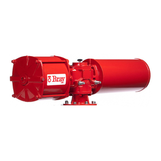
SERIES 98 & 98H SCOTCH YOKE ACTUATOR
Installation, Operation and Maintenance Manual
Provides instructions for installation, operation, and maintenance of the actuator.
1.0 DEFINITION OF TERMS
1.1 Hazard-free Use
Details precautions for safe operation and handling of the device.
1.2 Qualified Personnel
Defines the qualifications required for personnel handling the actuator.
2.0 INTRODUCTION
2.1 Storage
Guidelines for proper storage of the actuator to prevent damage and deterioration.
4.0 OPERATION GUIDELINES
CAUTION
Caution regarding pressurizing the cap end port of spring return actuators.
5.0 ASSEMBLY DRAWING AND MATERIALS OF CONSTRUCTION
5.1 Spring Return Pneumatic Actuator Assembly Drawing and Materials of Construction
Detailed assembly drawing and material specifications for pneumatic spring return actuators.
5.2 Spring Return Hydraulic Actuator Assembly Drawing and Materials of Construction
Detailed assembly drawing and material specifications for hydraulic spring return actuators.
6.0 MAINTENANCE
6.1 Lubricants and Maintenance Consumables
Lists recommended lubricants, sealants, and other consumables for maintenance.
6.2 Disassembly, Service & Reassembly of Modules
Procedures for disassembling, servicing, and reassembling actuator modules.
6.3 Spring Module
Details on the spring module, including warnings and removal/reassembly procedures.
6.4 Pressure Module
Information on the pressure module, including disassembly and reassembly.
6.5 Torque Module
Procedures for disassembling and reassembling the torque module.
6.6 Reassembly of Actuator
Steps for reassembling the entire actuator after module maintenance.
7.0 FIELD CONVERSIONS
7.1 Fail Safe Condition (for Spring Return Actuators)
Instructions for reversing the fail-safe direction of spring return actuators.
7.2 Double Acting to Spring Return
Procedure for converting a double-acting actuator to a spring-return type.
7.3 Spring Return to Double Acting
Procedure for converting a spring-return actuator to a double-acting type.
8.0 ASSEMBLY AND MATERIALS OF CONSTRUCTION - DOUBLE ACTING SINGLE CYLINDER
8.1 Pneumatic Actuator - Double Acting, Single Cylinder Assembly and Materials of Construction
Detailed assembly drawing and material specifications for double-acting single-cylinder pneumatic actuators.
8.2 Hydraulic Actuator - Double Acting, Single Cylinder Assembly and Materials of Construction
Detailed assembly drawing and material specifications for double-acting single-cylinder hydraulic actuators.
9.0 ASSEMBLY AND MATERIALS OF CONSTRUCTION - DOUBLE ACTING DUAL CYLINDER
9.1 Pneumatic Actuator - Double Acting, Dual Cylinder Assembly and Materials of Construction
Detailed assembly drawing and material specifications for double-acting dual-cylinder pneumatic actuators.
9.2 Hydraulic Actuator - Double Acting, Dual Cylinder Assembly and Materials of Construction
Detailed assembly drawing and material specifications for double-acting dual-cylinder hydraulic actuators.
10.0 BOLTING TORQUES AND TOOLS
10.1.a S98 Pneumatic Pressure Module
Bolting torques and tools for the S98 pneumatic pressure module.
10.2 Torque Module
Bolting torques and tools for the torque module.
10.3 Spring Module
Spring rod diameter, thread, and torque specifications for the spring module.
10.4 Actuator Assembly
ISO base, bolting sizes, and torques for the complete actuator assembly.
11.0 TECHNICAL DATA
11.1 S98 Double Acting Pneumatic Actuators
Technical data including operating pressure, volume, and weight for DA pneumatic actuators.
11.2 S98H Double Acting Hydraulic Actuators
Technical data including operating pressure, volume, and weight for DA hydraulic actuators.
11.3 S98 Spring Return Pneumatic Actuators
Technical data including operating pressure, volume, and weight for SR pneumatic actuators.
11.4 S98H Spring Return Hydraulic Actuators
Technical data including operating pressure, volume, and weight for SR hydraulic actuators.
12.0 MODULE WEIGHTS
12.1 Correct Valve Lifting / Strapping
Visual guide on correct methods for lifting and strapping the valve and actuator assembly.
13.0 A SERIES 98 PNEUMATIC DIMENSIONS
Series 98 Max Dimensions, inch
Table of maximum dimensions in inches for Series 98 pneumatic actuators.
Series 98 Max Dimensions, mm
Table of maximum dimensions in millimeters for Series 98 pneumatic actuators.
13.0 B SERIES 98 HYDRAULIC DIMENSIONS
Series 98H Max Dimensions, inch
Table of maximum dimensions in inches for Series 98H hydraulic actuators.
Series 98H Max Dimensions, mm
Table of maximum dimensions in millimeters for Series 98H hydraulic actuators.
13.1 Series 98/98H Dimensions - Bolting Pattern
Diagrams and specifications for actuator bolting patterns.
13.2 Valve Stem Interface Dimensions
Specifications for valve stem interface dimensions, including bore sizes.
14.0 SERIES 98/98H GENERAL SPECIFICATIONS AND FEATURES
14.1 Series 98 Seal Kits And Repair Kits
Lists part numbers for seal and repair kits for Series 98 pneumatic actuators.
14.2 Series 98H Seal Kits And Repair Kits
Lists part numbers for seal and repair kits for Series 98H hydraulic actuators.
15.0 HYDRAULIC OVERRIDE ON S98 PNEUMATIC ACTUATORS
15.1 Installation
General installation information for hydraulic override kits.
15.1.1 Installing Hydraulic Override on Spring Return Actuators
Step-by-step guide for installing hydraulic override on spring return actuators.
15.1.2 Operation - Spring Return Hydraulic Override
Instructions for operating the hydraulic override on spring return actuators.
15.2 Installing Hydraulic Override on DA Actuator
Step-by-step guide for installing hydraulic override on double-acting actuators.
15.2.1 Operation – DA Hydraulic Override
Instructions for operating the hydraulic override on double-acting actuators.
15.3 Maintenance of Hydraulic Override
Guidelines for the maintenance of hydraulic override systems.
15.3.1 Spring Return Hydraulic Override Cylinder
Maintenance procedures for the hydraulic cylinder in spring return overrides.
15.3.2 Disassembly of Hydraulic Cylinder
Steps for disassembling the hydraulic cylinder for maintenance.
15.3.3 Servicing Hydraulic Cylinder
Procedures for servicing the hydraulic cylinder, including seal replacement.
15.4 DA Override Cylinder
Information on the DA override cylinder, including disassembly.
15.4.1 Disassembly of Hydraulic Cylinder
Steps for disassembling the hydraulic cylinder for DA override systems.
16.0 JACKSCREW OVERRIDE
16.1 Installation
General information and steps for installing jackscrew override units.
16.1.1 Installing DA Jackscrew Override
Specific instructions for installing the jackscrew override on DA actuators.
16.1.2 Operating DA Jackscrew Override
Instructions for operating and testing the jackscrew override on DA actuators.
16.2 Installing SR Jackscrew Override
Specific instructions for installing the jackscrew override on SR actuators.
16.2.1 Operating SR Jackscrew Override
Instructions for operating and testing the jackscrew override on SR actuators.
17.0 EXTENDED STOPPERS
17.1 Installation
General information and steps for installing extended stopper modules.
17.1.1 Installing Extended Stopper for Torque Module
Instructions for installing extended stoppers on the torque module.
17.1.2 Adjusting Extended Stopper
How to adjust the position of the extended stopper.
17.2 Installing Extended Stopper for Spring Module
Instructions for installing extended stoppers on the spring module.
18.0 HYDRAULIC DAMPER
18.1 Installing the Hydraulic Damper on a DA actuator
Step-by-step guide for installing a hydraulic damper on DA actuators.
18.2 Installing the Hydraulic Damper on SR actuator
Step-by-step guide for installing a hydraulic damper on SR actuators.
19.0 PARTIAL STROKE TEST & LOCKING DEVICE
19.1 Installing PST &LD on a standard DA actuator
Instructions for installing the PST&LD module on standard DA actuators.
19.2 Configuring as a Locking Device to lock at CW end
Steps to configure the PST&LD module to lock the actuator at the CW end position.
19.3 Configuring as Locking Device at CCW end
Steps to configure the PST&LD module to lock the actuator at the CCW end position.
19.4 Configuring as a Partial Stroke Test Device at CCW end
Steps to configure the PST&LD module for partial stroke testing at CCW end.
19.5 Configuring as a Partial Stroke Test Device at CW end
Steps to configure the PST&LD module for partial stroke testing at CW end.
19.6 Installing PST & LD module on a standard SR actuator
Instructions for installing the PST&LD module on standard SR actuators.
19.7 Configuring as a Locking Device to Lock at CW End
Steps to configure the PST&LD module to lock the actuator at the CW end.
19.8 Configuring as Locking Device at CCW end
Steps to configure the PST&LD module to lock the actuator at the CCW end.
19.9 Configuring as a Partial Stroke Test Device at CCW end
Steps to configure the PST&LD module for partial stroke testing at CCW end.
19.10 Configuring as a Partial Stroke Test Device at CW end
Steps to configure the PST&LD module for partial stroke testing at CW end.
20.0 APPENDIX
20.1 Special Requirements for Actuators in Extended Temperature Service
Requirements for actuators used in extended temperature service, including flushing procedures.
Need help?
Do you have a question about the S98H Series and is the answer not in the manual?
Questions and answers