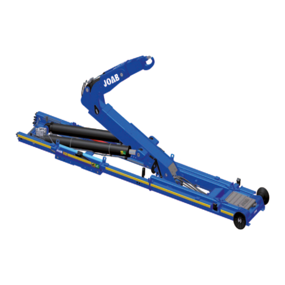
Summarization of Contents
Group 1: Replace Service Components
Replace Air and Hydraulic Filters
Procedure for cleaning and replacing air filter, hydraulic filter, and O-ring.
Replace High Pressure Filters
Instructions for replacing HF and LS high pressure filters based on pump type.
Drain and Refill Hydraulic Oil
Steps to drain and refill the hydraulic oil tank with new oil.
Group 2: Torque the Chassis Brackets
Inspect Chassis Bracket Shims
Check positioning and security of shims for chassis fastening brackets.
Torque Chassis Bracket Bolts
Ensure correct torque settings for all chassis bracket bolts and head bolts.
Group 3: Operation and Function Check
Check Lighting Functions
Verify all hook-lift lighting, including reverse lights, functions correctly.
Check Work Lights
Ensure the hook-lift's work lights are functioning properly.
Check Hydraulic Functions Under Load
Verify main hydraulic functions operate correctly under load, checking for leaks and noises.
Verify Control Stick Functions
Confirm all buttons on the hook-lift's control stick are functioning correctly.
Check Emergency Stop Button
Verify the emergency stop button functions correctly as described.
Test Emergency Stop System
Test the emergency stop mechanism to ensure it halts operation and can be reset.
Verify Display Panel LEDs
Check that all LEDs on the JOAB display panel are functioning correctly.
CBW Controller Specific Checks
Perform additional checks for CBW controller functions, screen, icons, and menus.
Check Trailer Warning Light LEDs
Verify the function of LEDs for trailer warning lights (optional equipment).
Verify Radio Controller Functions
Test the radio controller's functions, including emergency stop and LEDs.
Group 4: Inspection and Adjustment
Check Hook-Lift and Centre-Lock Function
Operate hook-lift and centre-lock through various positions to verify correct function.
Verify Centre-Lock Engagement
Inspect and verify that the centre-lock is fully engaged on both sides when the hook-lift is tipped.
Inspect Centre-Lock Gap
Measure the centre-lock gap in parked position to ensure it's within the 5-7 mm tolerance.
Verify Shunting Sensors
Check sensors for correct shunting operation and adjust if necessary.
Check Fast Lower Function
Verify the fast lower function slows to normal speed when the sensor is triggered.
Check Landing Brake Function
Inspect and verify the landing brake function and adjust the air cylinder if needed.
Inspect Main Valve Block
Inspect main valve blocks (air and electrically controlled) for actuators, valves, and connections.
Inspect Snow Plough Valve Block
Check snow plough valve block for magnet function and pressure build-up.
Verify Folding Hook-Post Function
Check folding hook-post and over-centre-valves for correct operation and leaks.
Check Extending Section
Check the extending section for hydraulic fluid leaks and welding damage.
Inspect Hook-Post and Hook
Inspect the hook-post and hook for damage, removing sharp edges.
Check Hook-Post Free Play
Verify the side-to-side free play in the hook-post is less than 10 mm.
Inspect Auxiliary Arms
Inspect auxiliary arms, cylinders, and fastening points for damage and smooth operation.
Inspect Shunting Axle Components
Check shunting axle housings, locking arms, and lock-pins for damage and wear.
Inspect Tip Cylinders
Inspect tip cylinders for scratches, damage, leaks, and bearing condition.
Check OC Valves for Leaks
Verify that OC valves for extending section and tip cylinders do not leak.
Inspect Frame Glide-Lugs
Inspect frame glide-lugs for damage and wear, removing sharp edges.
Operate and Verify Hydraulic Lock
Operate hydraulic lock, checking mechanical parts, free-play, and leaks.
Verify Spreader Flap/Deployer Function
Check spreader flap movement, return to parked position, and tolerances.
Inspect Tip Axle Bearings
Check tip axle bearings for wear, free-play, and grease point condition.
Verify Roller Movement and Bearings
Ensure rollers move freely and their bearings have no play.
Inspect Entire Frame Work
Inspect the entire hook-lift frame for cracks, welding damage, and joint integrity.
Verify Hydraulic Pump Function
Check hydraulic pump operation under load for noise, hose condition, and clamp tightness.
Inspect Hydraulic Tank
Ensure the hydraulic tank is secure and connections are leak-free.
Inspect Hydraulic System Hoses and Pipes
Check all hydraulic hoses, pipes, and connections for cracks and damage.
Inspect and Replace High Pressure Filter
Inspect high pressure filter container and replace the internal filter.
Check All Valves
Verify that all hook-lift valves function correctly and do not leak.
Inspect External Electrical/Hydraulic Panel
Inspect external panel's hydraulic quick-couplings and electrical connections.
Inspect Solenoid Boxes
Inspect solenoid boxes for cables, relays, valves, and fasteners for damage or corrosion.
Check Electrical Wiring
Inspect wiring harnesses, cables, and contacts for damage and secure connections.
Group 5: Hydraulic Pressure Control
Measure and Adjust Hydraulic Pressure
Measure and adjust hydraulic pressure to specified relief valve values.
Check By-Pass Valve Function
Verify the by-pass valve maintains system pressure above 2 bar when the pump is stopped.
Group 6: Lubrication
Lubricate Hook-Lift Points
Lubricate all specified lubrication points on Hook-Lift L and LA models.
Appendix 1: Control Stick Functions
CBW Controller Functions
Details the functions of the CBW controller's joystick and buttons.
Two Button Controller Functions (Electrical)
Explains the functions of the two-button electrical control system.
Two Button Controller Functions (Air)
Describes the functions of the two-button air control system.
Seven Button Controller Functions (Air)
Details the functions of the seven-button air control system.
Appendix 2: CBW User Interface
CBW User Interface Icon Definitions
Provides a list and meaning of icons used in the CBW controller's user interface.
Contact Information
Service Packets and Warranty Information
Information on ordering service packets and warranty details.


Need help?
Do you have a question about the L20 and is the answer not in the manual?
Questions and answers