Sign In
Upload
Download
Table of Contents
Contents
Add to my manuals
Delete from my manuals
Share
URL of this page:
HTML Link:
Bookmark this page
Add
Manual will be automatically added to "My Manuals"
Print this page
×
Bookmark added
×
Added to my manuals
Manuals
Brands
Joab Manuals
Lifting Systems
L Series
Service instruction
Joab L Series Service Instruction
Base service hook lifts
Hide thumbs
1
2
Table Of Contents
3
4
5
6
7
8
9
10
11
12
13
14
15
16
17
18
19
20
21
22
23
24
25
26
27
28
29
30
31
32
33
34
35
36
37
38
39
40
41
42
43
44
45
46
47
48
49
page
of
49
Go
/
49
Contents
Table of Contents
Bookmarks
Table of Contents
Table of Contents
Introduction
Overview
Required Equipment
Safety
Group 1 - Replace Service Components
Group 2 - Torque the Chassis Brackets
Group 3 - Operation and Function Check
Group 4 - Inspection and Adjustment
Round Sensors
Square Sensors
Group 5 - Hydraulic Pressure Control
Group 6 - Lubrication
Appendix 1 - Control Stick Functions
Electrical Controlled Systems - CBW Controller
Electrical Controlled Systems - Two Button Controller
Air Controlled Systems - Two Button Controller
Air Controlled Systems - Seven Button Controller
Appendix 2 - CBW User Interface
Icon Definitions
Safety Warnings
Contact Information
Service Packets and Warranty
Advertisement
Quick Links
1
Table of Contents
2
Introduction
3
Group 1 - Replace Service Components
4
Group 3 - Operation and Function Check
5
Group 5 - Hydraulic Pressure Control
6
Electrical Controlled Systems - Cbw Controller
Download this manual
13298 Edition 5 | 2019-10-20 | KM
JOAB Försäljnings AB
Östergärde Industriområde
www.joab.se
417 29 Göteborg
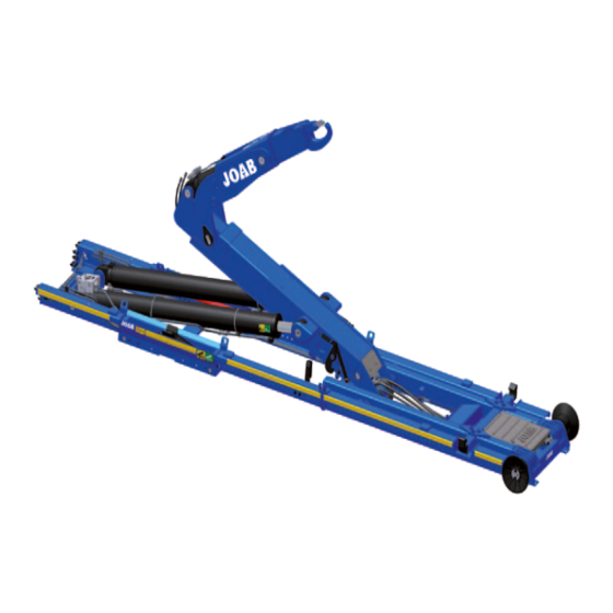
Base Service
Hook Lifts
L and LA
Telephone
Telefax:
031-705 06 00
031-705 06 09
E-post:
info@joab.se
Table of
Contents
Previous
Page
Next
Page
1
2
3
4
5
Advertisement
Table of Contents
Need help?
Do you have a question about the L Series and is the answer not in the manual?
Ask a question
Questions and answers
Related Manuals for Joab L Series
Lifting Systems Joab LA Series Service Instruction
Base service hook lifts (49 pages)
Lifting Systems Joab L26 Service Instruction
Base service hook lifts (49 pages)
Lifting Systems Joab L20 Service Instruction
Base service hook lifts (49 pages)
Lifting Systems Joab L24 Service Instruction
Base service hook lifts (49 pages)
Lifting Systems Joab EcoDrive Operation And Maintenance Manual
Hook-lifts (73 pages)
Lifting Systems Joab EcoDrive Hook-Lift L Service Manual
Base service (45 pages)
Lifting Systems Joab Hookmaster Manual
(59 pages)
Lifting Systems Joab EcoDrive Manual
Snow plough operation (2 pages)
Lifting Systems Joab VL10 Manual
Base service lift dumpers (33 pages)
Lifting Systems Joab EcoDrive VL10U Operation And Maintenance Manual
For skip-loaders (57 pages)
Lifting Systems Joab EcoDrive LA Operation And Maintenance Manual
For hooklifts (89 pages)
Lifting Systems Joab S8 Operation And Maintenance Manual
Hooklift (45 pages)
Lifting Systems Joab S10 Operation And Maintenance Manual
Hooklifts (49 pages)
Lifting Systems Joab Anaconda Twin User Instructions
(221 pages)
This manual is also suitable for:
La series
L18x
L26
L17
L20
L24
Table of Contents
Print
Rename the bookmark
Delete bookmark?
Delete from my manuals?
Login
Sign In
OR
Sign in with Facebook
Sign in with Google
Upload manual
Upload from disk
Upload from URL


Need help?
Do you have a question about the L Series and is the answer not in the manual?
Questions and answers