Table of Contents

Related Manuals for Joab EcoDrive LA


Summary of Contents for Joab EcoDrive LA
- Page 1 Operation and Maintenance Manual for Hooklifts 1021970 Edition 1 | 2022-02-04 | KM JOAB Försäljnings AB Telephone: Telefax: E-post: Östergärde Industriområde 031-705 06 00 031-705 06 09 info@joab.se www.joab.se 417 29 Göteborg...
- Page 2 EcoDrive 2.0 manual: 1021970 Edition 1 | 2022-02-04...
-
Page 3: Table Of Contents
Table of Contents Introduction Software Version About The Hook-Lift Correct Usage Hooklift Components LA-Model Hook-Lifts Optional Locking Mechanisms Manufacture Plate Design Body Standard Safety Operation CBW Controller User Interface Icon Definitions Page Setups Hook Positioning Function Buttons Background Light Warnings Control Stick Function Diagnostics And Statistics Menu Descriptions... - Page 4 Table of Contents Trailer Fast Lowering System - TFS Decentralized Hydraulic System - DHS Turtle Mode EcoDriveOptional Functions Position Memory System - PMS Fast Lowering System - FLS Fast Lowering System Plus - FLS+ Fast Tipper System - FTS Fast Drive System - FDS Fast Drive System Plus - FDS+ Service Online System - SOS Container Memory System - CMS...
- Page 5 Table of Contents Distributing A Load On A Body Loading A Body Tipping A Body Unloading A Body Shunting A Body Risk Of Damage Service And Maintenance Daily Maintenance Washing The Hook-Lift Lubrication Points Service Of The Hook-Lift Service Reminder - Sticker Service Reminder - CBW Controller Service Packets And Warranty Torquing Of Fasteners...
- Page 6 Table of Contents EcoDrive 2.0 manual: 1021970 Edition 1 | 2022-02-04...
-
Page 7: Introduction
This manual explains how to operate and maintain your EcoDrive Hook-Lift. It contains import- ant information for your own safety and the surrounding environment. JOAB’s products are characterised by a high level of safety, reliability, and long service-life. To get the best out of your EcoDrive Hook-Lift, we recommend reading this manual carefully. - Page 8 Introduction | Software Version viii EcoDrive 2.0 manual: 1021970 Edition 1 | 2022-02-04...
-
Page 9: About The Hook-Lift
It is important to verify that the vehicle has the correct axle distance and wheelbase. JOAB’s hooklifts are designed to transport dif- ferent types of bodies that have been man- ufactured according to the Swedish standard SS-3021. -
Page 10: Correct Usage
About the Hook-Lift | Correct Usage Correct Usage Incorrect use of JOAB's products can lead to material fatigue and cause excessive wear to the hydraulics and its components. The service life of the product can be reduced and in the worst- case lead to breakdown. -
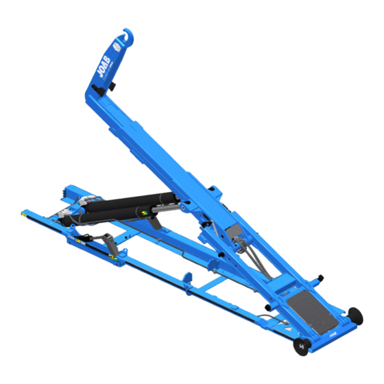
Page 11: Hooklift Components
About the Hook-Lift | Hooklift Components Hooklift Components The hooklift consists of the following main components: a frame, cylinders, auxiliary-lifting- arms, and a post with a lifting hook (made of high tensile steel). A. Intermediate section B. Hook C. Hook post D. -
Page 12: La-Model Hook-Lifts
The safety-hook is used to lock the hook onto the lifting bracket of a body and is operated from the cab. Optional Locking Mechanisms JOAB's hooklifts can be purchased with optional body locking devices. These options are in addition to the governing standards rel- evant to each country. -
Page 13: Design
All development and manufacture is per- formed by JOAB. We are ISO 9001 and ISO 14001 certified. A large proportion of our production is auto- mated. This guarantees high quality in the manufacturing process. - Page 14 About the Hook-Lift | Design JOAB's painting facilities meet all applicable environmental requirements. EcoDrive 2.0 manual: 1021970 Edition 1 | 2022-02-04...
-
Page 15: Body Standard
SS 3021. JOAB's hooklifts are designed to handle bodies that are manufactured in accordance with the Swedish standard SS 3021. Shown below are some of the more important requirements of the standard: SS 3021. - Page 16 Body Standard | The body must have a stop member that pre- vents the body from moving forwards and into the cab of the vehicle. Internal holes located in the body's frame members are used to lock the body onto a trailer.
-
Page 17: Safety
Do not make any modifications to the hook-lift as this can effect its structural properties. If a modification is required, contact JOAB for advice before making a modification to the hook-lift. EcoDrive 2.0 manual: 1021970 Edition 1 | 2022-02-04... - Page 18 Safety | EcoDrive 2.0 manual: 1021970 Edition 1 | 2022-02-04...
-
Page 19: Operation
The hooklift can also be controlled with the use of JOAB's radio controller or wired remote con- troller. These are not standard equipment and must be ordered as an extra option. For further information regarding the radio controller see "Radio Controllers", on page 35. -
Page 20: User Interface
Operation | CBW controller The mounting bracket is used to mount the unit inside the cab. Normally it is mounted onto the driver's A-post. However, it is also possible to mount it onto the driver's right arm rest (an extra cable is required to do this). - Page 21 Operation | CBW controller Table 2: User interface – icon description Icon Function Icon Function Night mode Automatic flap - VEHICLE* Work light - ON* . Read NOTE 2 below. Reverse light - ON* Tip trailer - UP* Automatic reverse light - ON Tip trailer - DOWN* Press 2 times to activate.
-
Page 22: Page Setups
If FFD is active, damage can occur. See "Friction Free Drive - FFD", on page 23 for further information. NOTE : This only applies to JOAB equipment installed on the hooklift. It does not apply to equipment installed by the manufacturer of the vehicle. NOTE For Scania vehicles, this can also be activated automatically when the vehicle is put into reverse. -
Page 23: Hook Positioning
Operation | CBW controller Table 3: Page setups (continued) Icon Description Icon Description Trailer setup Hook positioning display To switch between these page setups, simply press either the left or right arrow button below the display. The number of menu page setups that are accessible via the left and right arrow buttons can be configured as required (1–5 page setups). -
Page 24: Function Buttons
Operation | CBW controller Function Buttons Each of the five page setups in the user interface can be configured with six personal func- tions. The icons for the selected functions are placed at the bottom of the user interface (shown in white rectangles, see "User Interface", on page 12). -
Page 25: Control Stick Function
Operation | CBW controller Table 4: User interface warnings - icons (continued) Icon Meaning Icon Meaning The center-lock is open. Safety-hook is open (LA models). Table 5: User interface warnings - text Text Meaning The CBW controller has no communication with the CAN bus No CAN Communication network. - Page 26 Operation | CBW controller Table 6: CBW controller stick functions (continued) Tip Down Fast Tip Down Fast unload FLS(+) Push forwards Bottom button pressed Press the bottom button and and push forwards pull backwards. Trailer Tip Trailer Tip Fast load DOWN FDS+ Push the knob to the right...
-
Page 27: Diagnostics And Statistics
Operation | CBW controller Table 6: CBW controller stick functions (continued) Extending-Section Extending-Section Auto Cycle Load Turn the knob clockwise Turn the knob anti-clock- Top button pressed wise and push forwards Extra option, for further information see "EcoDriveOptional Functions", on page 24. LA models only. -
Page 28: Emergency Stop
In the event of a failure in the hook-lift’s system, it is possible to still operate the hook-lift using the emergency system. To activate the emergency system, follow the procedure listed below: If in any doubt about the use of the emergency override, contact JOAB for advice before using EcoDrive 2.0 manual: 1021970 Edition 1 | 2022-02-04... -
Page 29: Ecodrive Standard Functions
Operation | EcoDrive Standard Functions 1. Turn the hydraulic pump on. 2. Press and hold down the OK button for five seconds, to open the "Diagnostics and Statistics" page, as shown. 3. Press the down-arrow button so that the spanner icon is selected on the left menu. 4. -
Page 30: Ecodrive Pressure Control - Epc
Operation | EcoDrive Standard Functions EcoDrive Pressure Control - EPC The system is always operated using optimal hydraulic pressure. This is based on the function that is being operated. The system is self-calibrating and can work from 50 bar to 350 bar. Optimized pressure control allows for reduced response time. -
Page 31: Friction Free Drive - Ffd
Make sure that FFD is de-activated. It is possible to have FFD set so that it is deactivated at every system start. Contact JOAB service for more information about this. Tipper Safety System - TSS The auxiliary-lifting-arms are controlled using weight based damping. -
Page 32: Decentralized Hydraulic System - Dhs
Operation | EcoDriveOptional Functions Decentralized Hydraulic System - DHS EcoDrive's hydraulic system is modular. This has enabled a 30 % reduction in the number of hoses required, which in turn reduces the risk of damage to hoses. It also provides faster response times for certain functions. -
Page 33: Position Memory System - Pms
Operation | EcoDriveOptional Functions Position Memory System - PMS This function allows for the recording of shunting and tipping positions. Whenever PMS is act- ive, the hooklift will automatically stop at the saved position for shunting or tipping. Set the Shunting Position 1. -
Page 34: Fast Drive System - Fds
If it is possible, shunting will begin, as long as the bottom button is held down. Service Online System - SOS JOAB's Cloud solution for EcoDrive provides remote roadside assistance, regardless of your location. Container Memory System - CMS CMS ensures that the extending-section stops at a preset point when loading a container onto the hook-lift. -
Page 35: Active Plough Control - Apc
This can also be done with the use of JOAB's radio controller. To do so, simply press and hold down the hydraulic lock open button on the radio controller while operating the extending-section. Refer to "Radio Controllers", on page 35. -
Page 36: Icon Definitions Apc
Operation | EcoDriveOptional Functions Table 7: CBW controller stick - snow plough functions Side plough Side plough Front plough LEFT Bottom button pressed Push the knob right Turn the knob ant-clockwise Side plough Front plough Front plough DOWN RIGHT Top button pressed Pull the knob backwards Turn the knob clockwise Side plough... -
Page 37: Float Mode
The duration and rate of hydraulic flow for the automatic plough up function is set at factory, however, it can be calibrated if required. This must be done by a JOAB technician. EcoDrive 2.0 manual: 1021970 Edition 1 | 2022-02-04... -
Page 38: Slush Flaps
Operation | EcoDriveOptional Functions Slush Flaps If a snow plough is equipped with slush flaps, they can be activated by pressing the following icon . This activates a set of rubber flaps that are lowered below the bottom edge of the snow plough blade. -
Page 39: Autocycle System - Acs
Operation | EcoDriveOptional Functions Table 9: Hydraulic supply to tip trailer Icon Function Start the continuous-hydraulic-supply. The power-take-of must be active. Increase the continuous-hydraulic-supply Decrease the continuous-hydraulic-supply Stop the continuous-hydraulic-supply Autocycle System - ACS As an extra option, the cab controller can also be equipped with an automatic cycle function. This is used to load or unload a body in one continuous cycle. -
Page 40: Operation
Operation | Extendable Underrun Protection The hooklift can be equipped with asphalt driving mode. This allows the extending-section to move up and down when in tipping mode, which is ideally suited for asphalt work. It allows a asphalt container to extend into the asphalting machinery. Asphalt driving can be operated from different control sources, for example, it can also be operated using a radio controller. -
Page 41: External Plough Systems
However, they can also be retro fitted. If a retro fit is required, the hook-lift's main-valve-block will require software updates, and possibly additional JOAB hardware. For information regard- ing a retro fit, please take contact with JOAB's after sales department to discuss the options available. -
Page 42: Activating A Crane
Table 10: Crane lifting ability Crane Lifting Capacity (ton/meter) Dowel-Pins Required Dowel-pins can be retro-fitted. For information regarding this please contact JOAB after sales department. Activating a Crane Read and adhere to all safety warnings and operating instructions in the crane's oper- ator manual before operating a crane. -
Page 43: Radio Controllers
Radio Controllers A radio operated controller can be bought as an option for all EcoDrive Hook-Lifts. These allow for operation of the hooklift remotely. The operator does not need to be in the vehicle to oper- ate the hooklift. The use of a radio controller allows the operator to have a good visual overview of the lifting operation. -
Page 44: Display
Radio Controllers | Operation Buttons 9–12 are digital and used for simple functions, such as the operation of a spreader flap. The buttons 1–12 are functionalism. That is, they can have more than one function assigned to them. See "Function Mode" below. Display The display at the top of the controller displays information regarding the current function mode selected and the function currently activated. -
Page 45: Start The Radio Controller
Radio Controllers | Operation which function mode is operative, see Table 11, on page 36. If function mode 1 is active the LEDs for buttons 11 and 12 are not illuminated. Listed below is an overview of the buttons and their functions in relation to which function mode has been selected. -
Page 46: Fast Operation
This functionality must be ordered as an extra option, it is not standard. JOAB AB disclaims all responsibility if a vehicle is over weight, even if the radio controller displays a value that is lower then the maximum allowed for the vehicle. - Page 47 Radio Controllers | Operation Do not pull the controller out from the bottom. This will cause damage. EcoDrive 2.0 manual: 1021970 Edition 1 | 2022-02-04...
- Page 48 Radio Controllers | Operation EcoDrive 2.0 manual: 1021970 Edition 1 | 2022-02-04...
-
Page 49: Distributing A Load On A Body
Distributing a Load on a Body The operator of the hook-lift is responsible for handling it. Care must be taken to avoid injury or damage. Before operating the hook-lift make sure that you have read and are fully aware of the warnings in this manual and on the hook-lift. Before lifting a body with a load, make sure that: The load does not exceed the hooklift’s... - Page 50 Distributing a Load on a Body | The body must be covered if it contains loose material. There is a risk that loose material will be thrown off the vehicle if it is not covered. EcoDrive 2.0 manual: 1021970 Edition 1 | 2022-02-04...
-
Page 51: Loading A Body
Loading a Body The operator of the hook-lift is responsible for handling it. Care must be taken to avoid injury or damage. Before operating the hook-lift make sure that you have read and are fully aware of the warnings in this manual and on the hook-lift. FFD (Friction Free Drive) must be deactivated before loading a body that has dowel pins or an internal-mechanical-lock. - Page 52 Loading a Body | 5. Open the hydraulic lock. Once open, the hydraulic-lock-open icon is displayed in the CBW controller. 6. Operate the extending-section so that it retracts fully. The centre-lock will then open. 7. Verify that the centre-lock is open. The centre-lock-open icon is displayed in the CBW controller as shown, when it is open.
- Page 53 Loading a Body | 8. Operate the tip function so that the hook- post is in position ready for collecting the body. 9. LA models only: Before reversing towards the body's lift- ing-bracket, make sure that the safety- hook on the hook-post is open. 10.
- Page 54 Loading a Body | 14. Load the body onto the hooklift and fully extend the extending-section. To facilitate loading, the vehicle must be in neutral and free to roll in under the body. It is strictly forbidden to force or push the body up, especially with a heavy load.
- Page 55 Loading a Body | 17. Activate the hydraulic lock. 18. Inspect and make sure that hydraulic-lock has correctly secured the body onto the hooklift and that its warning icon is no longer illuminated on the CBW controller. 19. Turn the hydraulic pump OFF. EcoDrive 2.0 manual: 1021970 Edition 1 | 2022-02-04...
- Page 56 Loading a Body | EcoDrive 2.0 manual: 1021970 Edition 1 | 2022-02-04...
-
Page 57: Tipping A Body
Tipping a Body The operator of the hook-lift is responsible for handling it. Care must be taken to avoid injury or damage. Before operating the hook-lift make sure that you have read and are fully aware of the warnings in this manual and on the hook-lift. To tip a body follow the procedure listed below: 1. - Page 58 Tipping a Body | 6. Inspect and make sure that the body is secured with the hydraulic lock. The hydraulic lock must be closed. Verify that the warning icon in the cab, indicating that the hydraulic-lock is open, is not active. 7.
-
Page 59: Unloading A Body
Unloading a Body The operator of the hook-lift is responsible for handling it. Care must be taken to avoid injury or damage. Before operating the hook-lift make sure that you have read and are fully aware of the warnings in this manual and on the hook-lift. Before unloading a body, refer to and read "Distributing a Load on a Body", on page 41. - Page 60 Unloading a Body | 5. Operate the extending-section so that it fully retracts and the body is moved out- wards, as shown. The centre-lock will then open. Use the auxiliary-arms to reduce the fric- tion between the hooklift and the body. To do this, simply tip the body up a small amount to activate the auxiliary-arms.
- Page 61 Unloading a Body | when a low unloading angle is required. 8. Operate the extending-section and make sure that the hooklift's hook is free from the body's lifting-bracket. LA models only: Make sure that the safety catch has been released first. 9.
- Page 62 Unloading a Body | EcoDrive 2.0 manual: 1021970 Edition 1 | 2022-02-04...
- Page 63 Shunting a Body The operator of the hook-lift is responsible for handling it. Care must be taken to avoid injury or damage. Before operating the hook-lift make sure that you have read and are fully aware of the warnings in this manual and on the hook-lift. FFD (Friction Free Drive) must be deactivated before loading a body that has dowel pins or an internal-mechanical-lock.
- Page 64 Shunting a Body | 6. Operate the extending-section so that it fully retracts and the hook is moved out- wards, as shown. The centre-lock will then open. 7. Verify that the centre-lock is open. The centre-lock-open icon is displayed in the CBW controller as shown, when it is open.
- Page 65 Shunting a Body | 10. Reverse the vehicle as straight and as close as possible towards the trailer. Make sure not to damage to the trailer's tow-bar. 11. Use the extending-section and engage the hook-post with the body's lifting-bracket. 12. Inspect and verify that the hook-post is correctly engaged with the body's bracket. 13.
-
Page 66: Shunting A Body Risk Of Damage
Shunting a Body | Risk of Damage Use the auxiliary-arms, shown opposite, to help load the body and to reduce the fric- tion between the hooklift and the body. To do this, simply tip the body up a small amount so that the auxiliary-arms are activated. - Page 67 195 bar. A pressure relief valve can be installed to minimize this risk. A pressure relief vale is installed as standard on L26 models. For further information, contact JOAB. EcoDrive 2.0 manual: 1021970 Edition 1 | 2022-02-04...
- Page 68 Shunting a Body | Risk of Damage EcoDrive 2.0 manual: 1021970 Edition 1 | 2022-02-04...
-
Page 69: Service And Maintenance
Service and Maintenance To prevent unnecessary wear, it is important to maintain the hooklift continuously. Provided below is information regarding daily maintenance and servicing. Daily Maintenance Daily care, which only takes a few minutes, can prolong the service life of your hooklift. Provided below are some daily steps to help maintain the hooklift. -
Page 70: Washing The Hook-Lift
Service and Maintenance | Washing the Hook-Lift 5. Verify that all lighting and other electrical equipment functions correctly. 6. Finish by inspecting the hydraulic pump. If any damage is found, contact your JOAB workshop immediately. Washing the Hook-Lift Newly lacquered surfaces must be cleaned using detergent and a sponge only. -
Page 71: Lubrication Points
Service and Maintenance | Lubrication Points Lubrication Points The following image highlights the locations on the hooklift that shall be kept lubricated. Hook-Lift L Hook-Lift LA (optional) 1. Tip-cylinder (x 4) 10. Hook-post-cylinder (x 2) 2. Auxiliary-lift-arm (x 4) 11. Hook-post axle (x 2) 3. -
Page 72: Service Of The Hook-Lift
The air-filter should be replaced at least once every two years, or more often, as required. Service Reminder - Sticker A JOAB service sticker is placed on the inside of the drivers door to indicate when the hook-lift is due for its next service. In the example shown opposite, the numbers around the outside represent the months January to December. -
Page 73: Service Reminder - Cbw Controller
Refer to "Diagnostics and Statistics", on page 19. Service Packets and Warranty Service packets can be ordered from JOAB using the information provided below. Always have the information provided on the hook-lift's manufacture plate ready before making con- tact. Refer to "Manufacture Plate", on page 4. -
Page 74: Torquing Of Fasteners
Service and Maintenance | Working on the Hook-Lift Torquing of Fasteners All fasteners on the hooklift shall be re-torqued after 5000 km of operation. Vertical pendulum- bolts shall be re-torqued to 40 Nm. All other bolts shall be torqued as stated below. Table 14: Torque values for fasteners Threads Torque 8.8... - Page 75 Service and Maintenance | Working on the Hook-Lift The tip-support is anchored between the sub frame and the intermediate-section using two dowels, as anchor points. Locate these on the hooklift and place the tip-support between them, as shown above, before working on a hooklift.
- Page 76 Service and Maintenance | Working on the Hook-Lift EcoDrive 2.0 manual: 1021970 Edition 1 | 2022-02-04...
-
Page 77: Safety Warnings
Failure to do so can lead to serious injury or damage to equipment. Make sure that the labels are in good condition. If necessary, new safety labels can be ordered from JOAB. Safe Working Distance Make sure that there are no unauthorised persons in close prox- imity of the EcoDrive Hook-Lift's working area. - Page 78 Safety Warnings | Risk of being Trapped Be aware that there is a serious risk of becoming trapped when operating the hook-lift. Always verify that there is no risk of anyone becoming trapped or injured before operating the hook-lift. Extended-Tipping-Cylinders Before using the emergency operation function, Warning! It is not possible to operate the check and verify if the hook-lift is equipped with...
-
Page 79: Technical Data
Technical Data Specifications of the hooklift are provided below. Table 15: Specifications (L Series) Specification - L series Value Oil pressure 240 bar - 290 bar Recommended oil flow 100 l/min Maximum load capacity* 18 – 27 ton Maximum tip angle 44º... - Page 80 Technical Data | EcoDrive 2.0 manual: 1021970 Edition 1 | 2022-02-04...
-
Page 81: Fault Tracing The Hook-Lift
6. The tank’s air filter is blocked. 1. Insufficient amount of oil 1. Check the oil level. Poor lifting capacity to the pump 2. Contact JOAB. 2. Oil pressure too low. 3. Replace the cylinder gas- 3. Leaking cylinder gas- kets. kets. - Page 82 Fault Tracing the Hook-Lift | EcoDrive 2.0 manual: 1021970 Edition 1 | 2022-02-04...
-
Page 83: Appendix 1 - Diagnostics Page
Appendix 1 - Diagnostics Page Provided below is an overview of the various menu options provided in the Diagnostic and Stat- istics page. See also "Diagnostics and Statistics", on page 19. Usage Statistics This provides statistical information regarding the use of the hooklift, as follows: Ontime - how much time the hooklift has used the hydraulic supply from the pump. -
Page 84: Diagnostics
Appendix 1 - Diagnostics Page | Diagnostics Diagnostics This provides diagnostic information regarding sensors and input signals status for the hook- lift. Only standard sensors and sensors for com- mon extra options are displayed. All other addi- tional sensors for extra equipment are not. Inductive sensors are displayed with a green background whenever the system detects a sig- nal from it. -
Page 85: Emergency Operation & Calibration
If the hook-lift fails to work, it is possible to activate the fail safe mode. This turns off all sensors and allows the hook lift to be operated. WARNING: all safety features are disabled. JOAB takes no responsibility for damage caused when operating the hook-lift in this mode. To activ- ate the fail safe mode press buttons F3 and F4 simultaneously for five seconds. - Page 86 Appendix 1 - Diagnostics Page | Emergency Operation & Calibration EcoDrive 2.0 manual: 1021970 Edition 1 | 2022-02-04...
-
Page 87: Appendix 2 - Apc Transfer Kit
APC (Active Plough Control ). A APC kit, listed below, is required to do this. For information regarding the kit, please contact JOAB's, after sales department. The APC kit 1015550-3 contains the following items, that are required to install the CBW con- troller onto the driver's arm rest. - Page 88 Appendix 2 - APC Transfer Kit | Installation Procedure 7. Route the extension cable from the T-connector to the driver's right arm rest. Make sure that the cable is routed so that it will not be exposed to damage. 8. Connect the extension cable to the CBW controller's M12 connector. 9.
-
Page 89: Contact Information
Contact Information Information Details Address JOAB Försäljnings AB Östergärde Industriområde 417 29 Göteborg Sweden Telephone: 031-705 06 00 Tel fax: 031-705 06 09 E-mail: info@joab.se Website: www.joab.se Service and Warranty Claims For information regarding service and warranty claims, refer to "Service Packets and War- ranty", on page 65.
Need help?
Do you have a question about the EcoDrive LA and is the answer not in the manual?
Questions and answers