
Related Manuals for Joab EcoDrive Hook-Lift L


Summary of Contents for Joab EcoDrive Hook-Lift L
- Page 1 Base Service Hook Lifts 13301 Edition 1b | 2019-02-31 | KM JOAB Försäljnings AB Telephone Telefax: E-post: Östergärde Industriområde 031-705 06 00 031-705 06 09 info@joab.se www.joab.se 417 29 Göteborg...
- Page 2 Service Instruction: EcoDrive | 13301 Edition 1b | 2019-02-31...
-
Page 3: Table Of Contents
Table of Contents Introduction Overview Required Equipment Safety Group 1 – Replace Service Components Group 2 – Torque the Chassis Brackets Group 3 – Operation and Function Check Group 4 – Inspection and Adjustment Group 5 – Lubrication Safety Warnings Appendix 1 - CBW Control-Stick Main Functions Snow Plough Functions... - Page 4 Table of Contents Service Instruction: EcoDrive | 13301 Edition 1b | 2019-02-31...
-
Page 5: Introduction
This instruction is based on the original mounted equipment only. Refer to the relevant sup- plier’s documentation for all other optional or auxiliary equipment. JOAB takes no responsibility for consequences that occur due to work carried out by non-pro- fessionals. - Page 6 Introduction Service Instruction: EcoDrive | 13301 Edition 1b | 2019-02-31...
-
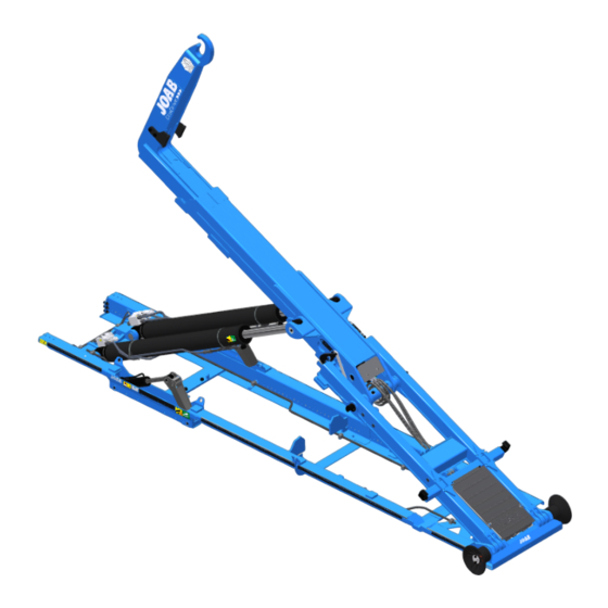
Page 7: Overview
Overview The following image provides an overview of the EcoDrive Hook-Lifts and its components. These components will be referred to throughout this procedure. Items marked with an aster- isk (*) are optional equipment. A. Sub frame H. Hydraulic-lock B. Auxiliary-lifting-arm I. -
Page 8: Safety
Overview Table 1: Required materials Material Required Quantity Part Number Viscosity Filter kit (Base) 1008902 Hydraulic filter - included in filter kit (1651) Air filter - included in filter kit (4650) O-ring (return filter) - included in filter kit (1631-3) High pressure filter kit 1008902-1 High pressure filter... -
Page 9: Group 1 - Replace Service Components
Group 1 – Replace Service Components Thoroughly clean the area around the cap for the air-filter (1) and the area around the hydraulic-filter (2), on the hydraulic tank. Then replace the following items with new ones: 1. The air filter. 2. - Page 10 Group 1 – Replace Service Components Service Instruction: EcoDrive | 13301 Edition 1b | 2019-02-31...
-
Page 11: Group 2 - Torque The Chassis Brackets
Group 2 – Torque the Chassis Brackets Inspect and make sure that all shims for the chassis's fastening brackets, where applicable, are not loose and correctly positioned. NOTE: Before the chassis brackets are first fastened, during assembly, the gap between them is measured, as shown below. If the gap is greater than 2 mm, shims are placed in between them before torquing of the bolts. - Page 12 Group 2 – Torque the Chassis Brackets Service Instruction: EcoDrive | 13301 Edition 1b | 2019-02-31...
-
Page 13: Group 3 - Operation And Function Check
Group 3 – Operation and Function Check Inspect the CBW controller and verify that it functions correctly as listed below: 1. Verify that the control-stick functions correctly. Check the up, down, left, right, and twist movements, as well as the two buttons on the control-stick. Verify that the control-stick centrers itself correctly after being moved. - Page 14 Group 3 – Operation and Function Check When operating the hook-lift's functions under load, listen to the vehicle's engine and hydraulic pump and verify that all functions as expected. Look for hydraulic leaks and listen for unusual noises. If the hook-lift is equipped with any of the following extra options, operate them and verify that they function correctly: 1.
- Page 15 Group 3 – Operation and Function Check 3. Verify that all applicable functions and their buttons work correctly. Provided below in Table 4 is a list of all functions available. Depending on the hook-lift being serviced, different functions will be applicable. A number of the functions listed below are optional.
- Page 16 Group 3 – Operation and Function Check If the vehicle is equipped with a tow-hitch, verify that the "Locked" and the "Open" LED lights function correctly on the tow-hitch LED panel, as shown below. NOTE: This is optional equipment. 3:10 Operate all external lights on the hook-lift and make sure that they function correctly, including the reverse lights.
-
Page 17: Group 4 - Inspection And Adjustment
Group 4 – Inspection and Adjustment Verify that the hook-lift and centre-lock function correctly. To do this, first operate the hook-lift as listed and shown below. Verify that each of the actions, 1-6, function cor- rectly. For information regarding the operation of the CBW controller, refer to: "Appendix 1 - CBW Control-Stick", on page 31. - Page 18 Group 4 – Inspection and Adjustment Lower the hook-lift back to its parked position and then inspect the centre-lock. Meas- ure the gap between the contact surfaces of the centre-lock as shown below. The gap must be between 2 mm – 6 mm. If it is not within the tolerance, it must be adjusted so that it is.
- Page 19 Group 4 – Inspection and Adjustment adjust as required, so that the sensor is positioned correctly with a tolerance of: 9 ± 3 mm. Make the measurement when the centre-lock is fully open. 3. Inspect and verify that the sensor for shunting, on the intermediate-section, is free from damage.
- Page 20 Group 4 – Inspection and Adjustment Inspect the ultra sonic sensor for the extending-section, where applicable. Make sure that it is positioned correctly and free from damage. NOTE: This is optional equipment. It is not standard. Verify that the ultra-sonic sensor functions correctly and that it stops the extending-sec- tion.
- Page 21 Group 4 – Inspection and Adjustment 3. Inspect and verify that the measurement between the extending-section and its end point, as shown below, is approximately 300 mm and that there is no risk of the extending-section making contact with the centre-lock. Verify that the folding-hook-post functions correctly, as follows: NOTE: This is only applicable to LA models.
- Page 22 Group 4 – Inspection and Adjustment 1. Check for hydraulic fluid leaks. 2. Inspect all welding for signs of damage. Inspect the hook-post and the hook for damage. Remove any sharp edges from the hook. 4:10 Check the free play in the hook-post, as shown below. The play must be less than 10 mm when moved from side-to-side, as shown below.
- Page 23 Group 4 – Inspection and Adjustment 2. Check for scratches, dis-colouring, and impact damage on the cylinders. 3. Check for hydraulic fluid leaks. 4. Check for damage to the mechanical components. 5. Inspect the fastening points for wear or damage. 4:12 Inspect the shunting axle components, as follows: 1.
- Page 24 Group 4 – Inspection and Adjustment 1. Check for scratches, dis-colouring, and impact damage on the tip cylinders. 2. Check for hydraulic fluid leaks. 3. Check the bearings on each end of the hydraulic cylinders. 4:14 Verify that the over-center-valves (OC) for both the extending-section and the tip cyl- inders do not leak, as follows.
- Page 25 Group 4 – Inspection and Adjustment 1. Inspect its mechanical parts for damage. 2. Check for free-play on the cylinder fastening points. 3. Check for free-play on the locking claws. 4. Check for hydraulic fluid leaks. 4:17 Verify that the spreader flap/deployer functions correctly, as follows: NOTE: This is optional equipment.
- Page 26 Group 4 – Inspection and Adjustment Verify that it does not protrude above the top face of the frame. 4:18 Inspect the tip axle's bearings, as follows: 1. Check the bearings for ware and excessive free-play. 2. Make sure that the grease points for the bearings are free from damage. 3.
- Page 27 Group 4 – Inspection and Adjustment 4:20 Inspect the hook-lift's entire frame work for damage, as listed below: 1. Check for damage in the frame work, such as cracks etc.. 2. Inspect all welded fastening points for damage to the welding. 3.
- Page 28 Group 4 – Inspection and Adjustment 4:25 Inspect the valve block and all connections for extra equipment such as a snow plough, salt spreader, or other equipment, where applicable. The valves for extra equipment are located above the hook-lift's main valve block on the bulk-head, as shown below.
- Page 29 Group 4 – Inspection and Adjustment 1. Turn the vehicle and hook-lift OFF. 2. Remove the protective cover from the rear-valve-block to gain access to it and its peripheral devices, as shown above. 3. Check the valve block and its connections for oil leaks and damage. Make sure that all hydraulic connections are correctly connected and do not leak.
- Page 30 Group 4 – Inspection and Adjustment 2. Inspect the hydraulic-pump's connections and hoses, to and from it. Verify that there is no damage. 3. Make sure that all hose clamps are correctly tightened. 4. Inspect and make sure there are no leaks. 4:29 Inspect the hydraulic tank as follows: 1.
- Page 31 Group 4 – Inspection and Adjustment 1. Inspect all hydraulic quick-couplings for the hook-lift and equipment, such as a snow plough. Verify that they function correctly, and do not leak. Make sure that they have protective caps, as shown below: 2.
- Page 32 Group 4 – Inspection and Adjustment Service Instruction: EcoDrive | 13301 Edition 1b | 2019-02-31...
-
Page 33: Group 5 - Lubrication
Group 5 – Lubrication Lubricate all of the hook-lift's lubrication points, as listed and shown below: Hook-Lift L Hook-Lift LA (optional) 1. Tip-cylinder (x 4) 10. Hook-post-cylinder (X 2) 2. Auxiliary-lift-arm (x 4)l 11. Hook-post axle (X 2) 3. Auxiliary-lift-cylinder (x 4) 4. - Page 34 Group 5 – Lubrication Service Instruction: EcoDrive | 13301 Edition 1b | 2019-02-31...
-
Page 35: Safety Warnings
Failure to do so can lead to serious injury or damage to equipment. Make sure that the labels are in good condition. If necessary, new safety labels can be ordered from JOAB. Safe Working Distance Make sure that there are no unauthorised persons in close proximity of the EcoDrive Hook-Lift's working area. - Page 36 Safety Warnings Extended-Tipping-Cylinders Warning! It is not possible to operate the Before using the emergency operation function, tip cylinders to their bottom position with check and verify if the hook-lift is equipped with a full stroke. The piston-rods will clash extended-tip-cylinders.
-
Page 37: Appendix 1 - Cbw Control-Stick
Appendix 1 - CBW Control-Stick Provided below is a table showing the main hook-lift functions and how they are operated. A table showing the Snow Plough Functions is also provided further down. Main Functions Table 5: CBW controller stick functions Tip Up Tip Up Extending-Section... -
Page 38: Snow Plough Functions
Appendix 1 - CBW Control-Stick Table 5: CBW controller stick functions(continued) Auto Cycle Automatic Fast Lower Unload* Lower Tip mode Shunting mode Top button pressed Top button pressed and hold forward for two Press the bottom button and push forward. and pull backwards seconds until the parked icon flashes Use only with an empty body. -
Page 39: Appendix 2 - Cbw User Interface
Appendix 2 - CBW User Interface Provided below is an overview of the CBW controller's user interface. For more information regarding the operation of the user interface, refer to the operator's manual. Icon Definitions Provided below is a list of the functions available in the user interface and their meaning. Note, not all functions listed below are activated for all installations. - Page 40 Appendix 2 - CBW User Interface Table 7: User interface – icon description(continued) Icon Function Icon Function Flashing light - ON Draw bar* Red light - ON Hydraulic-lock - CLOSE Center lock is OPEN Hydraulic-lock - OPEN Safety hook is OPEN* Automatic flap - VEHICLE* Hydraulic-lock is OPEN Continuous-hydraulic-supply (start/stop)*...
-
Page 41: Emergency Operation
If in any doubt about the use of the emergency over- ride, contact JOAB for advice before using it. 1. Turn the hydraulic pump on. 2. Press and hold down the OK button for five seconds, to open the "Diagnostics and Statistics"... - Page 42 Appendix 2 - CBW User Interface Service Instruction: EcoDrive | 13301 Edition 1b | 2019-02-31...
-
Page 43: Contact Information
E-mail: info@joab.se Website: www.joab.se Service Packets and Warranty Service packets can be ordered from JOAB using the information provided below. Always have the information provided on the hook-lift's manufacture plate ready before making con- tact. Table 8: Service packets Department Contact Details JOAB Göteborg... - Page 44 JOAB Täby (Stockholm – North) Technical Support telephone: +46 873-25875 JOAB Täby (Stockholm – North) Service telephone: +46 863-08871 Visit our website: www.joab.se to order spare parts and find your nearest JOAB authorised workshop. Service Instruction: EcoDrive | 13301 Edition 1b | 2019-02-31...
- Page 45 Contact Information Service Instruction: EcoDrive | 13301 Edition 1b | 2019-02-31...
Need help?
Do you have a question about the EcoDrive Hook-Lift L and is the answer not in the manual?
Questions and answers