
Related Manuals for Festo VMPA-KMS2-24 Series


Summary of Contents for Festo VMPA-KMS2-24 Series
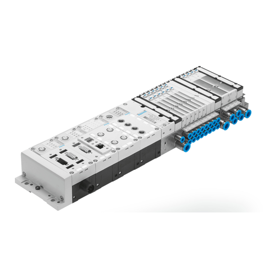
- Page 1 Valve terminal MPA-S/MPA-F Brief description MPA-S/MPA-F with multipin connector type: MPA...-MPM-VI – English 8080182 2017-12d [8080184]...
- Page 2 Translation of the original instructions Documentation on the product For all available product documentation è www.festo.com/pk Copyright: Festo SE & Co. KG Ruiter Straße 82 73734 Esslingen Germany Internet: http://www.festo.com E-Mail: service_international@festo.com Reproduction, distribution or sale of this document or communication of its contents to others without express authorization is prohibited.
- Page 3 IEC/DIN EN 60204-1 Observe also the general requirements for PELV power circuits as per IEC/DIN EN 60204-1. Please note Commission only a valve terminal which has been fitted and wired completely. Festo MPA...-MPM-VI 2017-12d English...
- Page 4 Do not exceed the maximum permitted signal cable length of 10 m. Recommendation: Use the following 25-pin multipin socket with cable from the Festo range of acessories for connecting the MPA valve terminal with multipin connection: Multipin socket with cable VMPA-KMS1-8-...
- Page 5 BN BU WH RD GY PK BN RD RD BU WH BK WH GN BN GN WH YE 0 V for positive-switching control signals; 24 V for negative- switching control signals; mixed operation is not permitted. Festo MPA...-MPM-VI 2017-12d English...
- Page 6 MPA 2 one address VMPA1-MPM-EMM-4 VMPA2-MPM-EMM-2 two addresses VMPA1-MPM-EMM-8 VMPA2-MPM-EMM-4 – If an electronic module occupies 2 addresses, the following applies: – pilot solenoid 14 occupies the lower-value address; – pilot solenoid 12 occupies the higher-value address. Festo MPA...-MPM-VI 2017-12d English...
- Page 7 2 (4 valve locations) Electronic module 1 VMPA1-MPM-EMM-8 1 VMPA2-MPM-EMM-4 1 VMPA1-MPM-EMM-4 1 VMPA2-MPM-EMM-2 For controlling the valves, each valve solenoid coil (referred to in the following as coil) is assigned to a certain pin of the multipin plug. Festo MPA...-MPM-VI 2017-12d English...
- Page 8 Address Valve location Coil Electronic module number VMPA1-MPM-EMM-8 VMPA2-MPM-EMM-2 VMPA1-MPM-EMM-4 VMPA2-MPM-EMM-4 0 V for positive-switching control signals; 24 V for control signals; mixed operation is not permitted. Festo MPA...-MPM-VI 2017-12d English...
- Page 9 Pin assignment with electronic module VMPA2-MPM-EMM-2 Unused valve location occupies one address per valve location Pin assignment with electronic module Pin assignment with electronic VMPA2-MPM-EMM-4 module VMPA1-MPM-EMM-8 occupies two addresses occupies two addresses per per valve location valve location Festo MPA...-MPM-VI 2017-12d English...
- Page 10 – Immunity to interference 1) Dimensions and materials: See Pneumatics Manual 2) Maximum 24 valve solenoid coils can be controlled 3) The valve terminal is intended for industrial usage 4) The maximum permitted signal cable length is 10 m Festo MPA...-MPM-VI 2017-12d English...
Need help?
Do you have a question about the VMPA-KMS2-24 Series and is the answer not in the manual?
Questions and answers