
Related Manuals for Festo MPA-ASI-VI


Summary of Contents for Festo MPA-ASI-VI
- Page 1 MPA-S Valve Terminal Manual pneumatics MPA-S Valve terminal with MPA-S pneumatics Type: MPA-FB-... MPA-CPI-... MPA-MPM-... and MPA-ASI-... Manual 534 241 en 1108e [750 435]...
- Page 3 ....... . . 534 241 © (Festo AG & Co. KG, D-73726 Esslingen, Germany, 2011) Internet: http://www.festo.com E-Mail: service_international@festo.com...
- Page 4 Contents and general instructions Festo P.BE-MPA-EN en 1108e...
-
Page 5: Table Of Contents
......1-40 1.6.3 Proportional-pressure regulator with LCD display ... . . 1-41 Festo P.BE-MPA-EN en 1108e... - Page 6 MPA-S valve terminal with CPI module or AS-Interface ..3-32 3.5.3 MPA-S valve terminal with multi-pin plug connection ... 3-32 Festo P.BE-MPA-EN en 1108e...
- Page 7 ......5-40 5.4.6 Adding a proportional pressure regulator ....5-41 Festo P.BE-MPA-EN en 1108e...
- Page 8 ............Festo P.BE-MPA-EN en 1108e...
-
Page 9: Intended Use
CE marking symbol. Standards and test values, which the product observes and fulfils, can be found in the section “Technical data”. The product-relevant EU directives can be found in the declaration of conformance. Festo P.BE-MPA-EN en 1108e... -
Page 10: Target Group
– The technical data in this documentation may show values deviating from this. Target group This manual is directed exclusively toward technicians trained in control and automation technology. Service Please consult your local Festo repair service if you have any technical problems. VIII Festo P.BE-MPA-EN en 1108e... -
Page 11: Instructions On This Manual
CPX module. An overview is provided in the system description of your CPX terminal, in the “Descriptions of the CPX terminal” table. – MPA-S with multi-pin plug connection, CPI interface, AS interface: in the respective package insert Festo P.BE-MPA-EN en 1108e... -
Page 12: Important User Instructions
... means that failure to observe this instruction may result in damage to property. The following pictogram marks passages in the text which describe activities with electrostatically sensitive devices: Electrostatic sensitive devices: inappropriate handling can result in damage to components. Festo P.BE-MPA-EN en 1108e... - Page 13 Pictograms Information: Recommendations, tips and references to other sources of information. Accessories: Information on necessary or useful accessories for the Festo product. Antipollution: Information on environment-friendly use of Festo products. Text designations Bullet points indicate activities that may be carried out in •...
- Page 14 – with holes for H-rail and wall mounting Exhaust plate Plate for ducted exhaust with connection (3/5) Input/output modules Manual override MPA1 or MPA2 Size of the valves: MPA1 = 10 mm, MPA2 = 20 mm. Festo P.BE-MPA-EN en 1108e...
- Page 15 – size MPA1 (type MPAS...4) with 4 valve locations – size MPA2 (type MPAS...2) with 2 valve locations Tubing connection Connecting the pneumatic supply lines (tubing) to the MPA-S valve terminal Valve Monostable, bistable or mid-position valves Tab. 0/1: Product-specific terms and abbreviations XIII Festo P.BE-MPA-EN en 1108e...
- Page 16 Contents and general instructions Festo P.BE-MPA-EN en 1108e...
-
Page 17: Summary Of Components
Summary of components Chapter 1 Summary of components Festo P.BE-MPA-EN en 1108e... - Page 18 ......1-40 1.6.3 Proportional-pressure regulator with LCD display ... . . 1-41 Festo P.BE-MPA-EN en 1108e...
-
Page 19: The Mpa-S Valve Terminal
1. Summary of components The MPA-S valve terminal Festo supports your automation tasks at machine level with the MPA-S valve terminal. The modular structure of the MPA-S valve terminal enables you to match this valve terminal optimally to your machine or system. -
Page 20: Overview Of Variants
A max. of 64 solenoid coils can be supplied. A max. of 128 solenoid coils can be supplied. Tab. 1/1: Number of valve locations of the MPA-S valve terminal with CPX terminal Fig. 1/1: MPA-S valve terminal with CPX terminal Festo P.BE-MPA-EN en 1108e... - Page 21 A max. of 24 solenoid coils can be supplied. A max. of 32 solenoid coils can be supplied. Tab. 1/2: Number of valve locations of the MPA-S valve terminal with CPI module Fig. 1/2: MPA-S valve terminal with CPI interface Festo P.BE-MPA-EN en 1108e...
- Page 22 A maximum of 24 solenoid coils can be actuated. The electrical connection of the solenoid coils is made centrally via the multi-pin plug connector. Tab. 1/3: Number of valve locations on the MPA-S valve terminal with multi-pin plug connection Fig. 1/3: MPA-S valve terminal with multi-pin plug connection Festo P.BE-MPA-EN en 1108e...
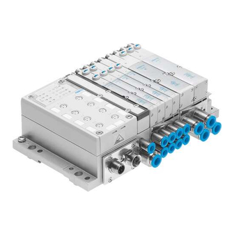
- Page 23 A max. of 4 solenoid coils can be supplied. A max. of 8 solenoid coils can be supplied. Tab. 1/4: Number of valve locations on the MPA-S valve terminal with AS interface Fig. 1/4: MPA-S valve terminal with AS interface Festo P.BE-MPA-EN en 1108e...
-
Page 24: Valve Terminal Design
Cover plate Pneumatic supply plate Valves Pressure regulator plate Pressure sensor plate Sub-base Electrical supply plate Multiple connector plate; AS interface, CPI interface or pneumatic interface Proportional-pressure regulator Fig. 1/5: Main components of the MPA-S valve terminal Festo P.BE-MPA-EN en 1108e... -
Page 25: Description Of Components
CPX terminal: LED-/LCD proportional-pressure Electrical supply plate regulator or blanking plate Seal (optional separating seal for Right end plate pressure zone separation) Fig. 1/6: Components of the MPA-S valve terminal with CPX terminal or CPI module, level Festo P.BE-MPA-EN en 1108e... - Page 26 Exhaust plate (3/5) or flat plate Valve or blanking plate silencer Vertical pressure isolating plate Electronic module with LEDs Pressure regulator plate Fig. 1/7: Components of the MPA-S valve terminal with CPX terminal or CPI module, level 1-10 Festo P.BE-MPA-EN en 1108e...
- Page 27 Sub-base with work connections and electric linking Pneumatic supply plate Seal (optionally isolating seal for Inscription label with support forming pressure zones) Fig. 1/8: Components of the MPA-S valve terminal with electric multi-pin or AS interface 1 level 1-11 Festo P.BE-MPA-EN en 1108e...
- Page 28 Exhaust plate (3/5) or flat plate Vertical pressure isolating plate silencer Pressure regulator plate Valve or blanking plates Electronic module with LEDs Fig. 1/9: Components of the MPA-S valve terminal with electric multi-pin or AS interface 2 level 1-12 Festo P.BE-MPA-EN en 1108e...
- Page 29 Sub-D consists of the following electric components: Multi-pin plug socket with cable Electrical part of the multiple connector plate with Sub-D connection Fig. 1/11: Electric components of the MPA-S valve terminal with multi-pin plug connection Sub-D 1-13 Festo P.BE-MPA-EN en 1108e...
-
Page 30: Valves
Identifying the valves The valves on the MPA-S valve terminal are marked by identification codes. By means of this identification on the front of the valve, you can ascertain the equipment fitted on your MPA-S valve terminal. 1-14 Festo P.BE-MPA-EN en 1108e... - Page 31 Monostable 3/2-way valve, normally open, external compressed air supply via connection (2), pneumatic spring return Monostable 3/2-way valve, normal position closed, external compressed air supply via connection (4)), pneumatic spring return Tab. 1/5: Identification codes of the valves 1-15 Festo P.BE-MPA-EN en 1108e...
-
Page 32: Proportional-Pressure Regulator
Configure the proportional pressure regulator via the PLC or the Festo Handheld (CPX-MMI). Mounting of the proportional-pressure regulator is described in the mounting instructions VPPM-...TA-... Information on configuring the proportional-pressure regulator is provided in the MPA-... -
Page 33: Pressure Sensor Plate
The limits for pressure monitoring are set by means of parameter settings. The pressure sensor plate can be parametrised via the PLC or the Festo Handheld (CPX-MMI). Mounting of the pressure sensor plate is described in the mounting instructions VMPA-FB-PS-... -
Page 34: Pneumatic Supply Plate
MPA-S valve terminal the pilot air supply for pilot control of the valves is supplied centrally via the corresponding electrical interface (pneumatic interface, multiple connector plate, AS interface or CPI interface). 1-18 Festo P.BE-MPA-EN en 1108e... - Page 35 – MPA1: after the second valve position – MPA2: after the first valve position. The sub-bases are available in the following designs: – only supply channel (1) separate – supply channel (1) and exhaust channels (3) and (5) separate 1-19 Festo P.BE-MPA-EN en 1108e...
- Page 36 Sub-base with separate supply Type: VMPA1-FB-AP-4-1-T1 Type: VMPA2-FB-AP-2-2-T0 channel (1) Sub-base with separate supply Type: VMPA1-FB-AP-4-1-S1 Type: VMPA2-FB-AP-2-2-S0 channel (1) and separate exhaust channels (3) and (5). Tab. 1/7: Variants of the sub-bases with pressure zone separation 1-20 Festo P.BE-MPA-EN en 1108e...
- Page 37 You can recognize whether your MPA-S valve terminal is equipped with pressure zones, and if so how many either by the marking on the sub-base (see Tab. 1/7) or by the marking on the seal (see Tab. 1/8). 1-21 Festo P.BE-MPA-EN en 1108e...
- Page 38 (Ident. code I) blocked (Ident. code S) Separating seal, channels (3) and (5) Without marking Seal with blocked (Ident. code R) open channels (1), (3) and (5) Tab. 1/8: Marking of the seal variants for the sub-bases 1-22 Festo P.BE-MPA-EN en 1108e...
-
Page 39: Vertical Stacking
1.4.7 Vertical stacking You can fit further pneumatic components to each valve position between the sub-base and the valve. These components will enable you to implement certain additional effects as desired. The following components are available: 1-23 Festo P.BE-MPA-EN en 1108e... - Page 40 The following section describes the functions of the vertical pressure shut-off plate. Sub-base type MPA...-...-AP-... with electronic module type VMPA...-...EM... For notes on installing the vertical stacking components, see Chapter 3 Tab. 1/9: Components of the pneumatic module of the MPA-S valve terminal 1-24 Festo P.BE-MPA-EN en 1108e...
- Page 41 The circuit symbol of the vertical pressure shut-off plate can be found in Appendix B, Tab. B/7. Instructions on installation of the vertical pressure shut-off plate can be found in the assembly instructions VMPA1-HS. 1-25 Festo P.BE-MPA-EN en 1108e...
- Page 42 Tab. 1/10: Identification of the pressure regulator plates in the type code The circuit symbol of the pressure regulating valve is provided in Appendix B, Tab. B/5. Instructions on the installation of the pressure regulator plates are provided in the assembly instructions VMPA...-B8-R...C2-C... 1-26 Festo P.BE-MPA-EN en 1108e...
- Page 43 – An equal working pressure is required at working lines (2) and (4). – A lower air pressure (e.g. 3 bar) is required than the operating pressure present at the valve terminal (e.g. 8 bar). 1-27 Festo P.BE-MPA-EN en 1108e...
- Page 44 (2) of the sub-base. The unregulated exhaust air is then fed via channel (4) through the pressure regulator plate and then to channel (5) and vented. 1-28 Festo P.BE-MPA-EN en 1108e...
- Page 45 1. Summary of components Pressure regulator Intermediate plate Valve Sub-base Fig. 1/12: B-pressure regulator 1-29 Festo P.BE-MPA-EN en 1108e...
- Page 46 (1) to channel (5) Rev. B-pressure in channel (3) in channel (5) from channel (2) via regulator channel (1) to channel (3) Tab. 1/11: Mode of operation of the reversible A or B pressure regulating valve 1-30 Festo P.BE-MPA-EN en 1108e...
- Page 47 – When fast venting is required. – When the pressure regulator must always be adjustable. Fig. 1/13 shows the following switching position of the reversible B pressure regulating valve: 1-31 Festo P.BE-MPA-EN en 1108e...
- Page 48 The unregulated exhaust air is switched inside the valve from channel (4) to channel (1) and then in the intermediate plate to channel (3). Pressure regulator Intermediate plate Valve Sub-base Fig. 1/13: Reversible B pressure regulating valve 1-32 Festo P.BE-MPA-EN en 1108e...
-
Page 49: Operation And Connection Elements
VMPA-FB-PS-P1 Connection (82/84) only with variant for ducted exhaust, “Pilot exhaust” Pilot connection (12/14), “External pilot air supply” Supply port (1), “Operating pressure” Fig. 1/14: Pneumatic connecting and operating elements of the MPA-S valve terminal 1-33 Festo P.BE-MPA-EN en 1108e... -
Page 50: Manual Override (Mo)
Cover cap, concealed This cover cap completely covers the MO, which is thus secured against undesired actuation. Mounting of the MO cover caps is described in Chapter 4.4. 1-34 Festo P.BE-MPA-EN en 1108e... - Page 51 Pressure gauge (optional) Connection M5 with blanking plug Connection for pressure gauge (can be turned 90°) Connection M5 with QS-fitting Fig. 1/15: Operating and connection elements of the pressure regulator plates 1-35 Festo P.BE-MPA-EN en 1108e...
- Page 52 Sub-D connection Fig. 1/16: Electric connecting elements of MPA-S valve terminal with multi-pin plug connection Information on the electronics module of the MPA-S valve terminal can be found in the MPA-... electronics descriptions. 1-36 Festo P.BE-MPA-EN en 1108e...
-
Page 53: Display Components
Fig. 1/17: Electric display elements of MPA-S valve terminal with multi-pin plug connection or with AS interface Information on the electric connecting and display elements of the AS interface can be found in the package insert. 1-37 Festo P.BE-MPA-EN en 1108e... - Page 54 Signal status display of the pilot solenoids Optional additional electrical red: Error display supply: Valve load voltage connection Fig. 1/18: Electric connecting and display elements of the MPA-S valve terminal with CPX terminal or CPI module 1-38 Festo P.BE-MPA-EN en 1108e...
- Page 55 The pressure sensor plate has the following display elements: Pressure sensor plate Red LED: Pressure exceeded Green LED: Pressure conformed to Red LED: Pressure too low Red LED: Common error display Fig. 1/19: Display elements of the pressure sensor plate 1-39 Festo P.BE-MPA-EN en 1108e...
-
Page 56: Proportional-Pressure Regulator
1. Summary of components 1.6.2 Proportional-pressure regulator The LED proportional pressure regulator has the following display elements: Green power LED Proportional-pres sure regulator Red error LED Fig. 1/20: Display elements of the proportional pressure regulator 1-40 Festo P.BE-MPA-EN en 1108e... -
Page 57: Proportional-Pressure Regulator With Lcd Display
The proportional-pressure regulator with LCD display has the following operation and display components: Proportional- pressure regulator Display DOWN button EDIT button UP button Red error LED Fig. 1/21: Operation and display components of the LCD proportional-pressure regulator 1-41 Festo P.BE-MPA-EN en 1108e... - Page 58 “Exxx” is displayed in the numbers field. In this case, xxx stands for the display switch-off time in seconds. The display exposure time can now be set with the UP and DOWN keys. The setting range lies between OFF and 999 seconds. 1-42 Festo P.BE-MPA-EN en 1108e...
- Page 59 Fitting Chapter 2 Fitting Festo P.BE-MPA-EN en 1108e...
- Page 60 ....2-11 Mounting/removing the inscription label holder ..... . 2-13 Festo P.BE-MPA-EN en 1108e...
-
Page 61: Fitting
Handle all modules and components of the MPA-S valve terminal with great care. Pay particular attention to the following: – The specified torques must be complied with. – Electrostatically sensitive devices. Therefore, do not touch any contact surfaces. Festo P.BE-MPA-EN en 1108e... -
Page 62: Mounting Variants
Tab. 2/1: Mounting methods of the MPA-S valve terminal Note Mount the MPA-S valve terminal so that there is sufficient space for heat dissipation and ensure that the maximum limits for temperatures are observed (see Technical data). Festo P.BE-MPA-EN en 1108e... -
Page 63: Mounting/Dismounting On H-Rails
MPA-S valve terminal with multi-pin plug connection: CPA-BG-NRH. This kit contains 2 M4x10 screws and 2 clamping components. – MPA-S valve terminals with CPX terminal: CPX-CPA-BG-NRH. This kit contains 3 clamping components and 3 M4x10 screws. Festo P.BE-MPA-EN en 1108e... - Page 64 2. Mount the H-rail (DIN mounting rail EN 60715 - 35x7.5; width 35 mm, height 7.5 mm). Make sure there is sufficient space for connecting the power supply cables and tubing. Fasten the H-rail to the mounting surface at intervals of approx. every 100 mm. Festo P.BE-MPA-EN en 1108e...
- Page 65 6. Turn the clamping components for mechanical locking vertically behind the H-rail (see Fig. 2/2, arrow A); then tighten the retaining screws of the H-rail clamping with 1.3 Nm to secure the MPA-S valve terminal against tilting or sliding. Festo P.BE-MPA-EN en 1108e...
- Page 66 H-rail. 2. Swing the MPA-S valve terminal forwards away from the H-rail (see Fig. 2/3). 3. Lift the MPA-S valve terminal away from the H-rail (see Fig. 2/3). Festo P.BE-MPA-EN en 1108e...
-
Page 67: Mounting/Dismounting On Walls
Note Overloading of mounting holes or natural resonance with oscillations can cause damage. Besides the instructions on standard fastening points in • Chapter 2.2.3, also observe the instructions on additional fastening in Chapter 2.2.4. Festo P.BE-MPA-EN en 1108e... -
Page 68: Standard Fastening Points Of The Valve Terminal
MPA-S valve terminal with CPX terminal Required mounting: – End plates: two M4 1 or M6 screws 2 each – Pneumatic interface: two M4 screws 1 Tab. 2/3: Methods of fastening the MPA-S valve terminal 2-10 Festo P.BE-MPA-EN en 1108e... -
Page 69: Additional Fastening Of The Valve Terminal
For MPA-S valve terminals that exceed a length of 280 mm – For increased vibration/shock loads (for limits for vibration and shock, see Appendix A) Tab. A/2 – For MPA-S valve terminals equipped with four or more CPX interlinking blocks 2-11 Festo P.BE-MPA-EN en 1108e... - Page 70 With four or more CPX interlinking blocks, the mounting clip type CPXBG-RW-... must be used as an additional fastener (see system description for the CPX terminal). Tab. 2/4: Additional fastening points of the MPA-S valve terminal 2-12 Festo P.BE-MPA-EN en 1108e...
-
Page 71: Mounting/Removing The Inscription Label Holder
An inscription label holder can be mounted onto each sub-base to enable the valves or work connections to be distinguished. Information on accessories can be found in the Festo Catalogue (see www.festo.com\catalogue). Mounting Proceed as follows: Clip the inscription label holders into the grooves in the •... - Page 72 (blade width max. 3.5 mm) to press down the snap hook (see diagram). Hole for unlocking the inscription label holder Inscription label holder Fig. 2/5: Removing the inscription label holder 3. Pull the inscription label holder out of the fixture in the sub-base. 2-14 Festo P.BE-MPA-EN en 1108e...
- Page 73 Installation Chapter 3 Installation Festo P.BE-MPA-EN en 1108e...
- Page 74 MPA-S valve terminal with CPI module or AS-Interface ..3-32 3.5.3 MPA-S valve terminal with multi-pin plug connection ... 3-32 Festo P.BE-MPA-EN en 1108e...
-
Page 75: Installation
5 mg/m (see ISO 8573-1 class 4). This avoids operative malfunction of the valves. Excessive residual oil is not permissible irrespective of the compressor oil, as otherwise the basic lubrication will be washed out with time. Festo P.BE-MPA-EN en 1108e... -
Page 76: Operation With Lubricated Compressed Air
Incorrect additional oil and too much residual oil content in the compressed air will reduce the service life of the valve terminal. – Use Festo special oil OFSW-32 or the other oils listed in the Festo catalogue (as per DIN 51524-HLP32, basic viscosity 32 CST at 40 °C). - Page 77 Another indicator of over-lubrication is the coloration or the condition of the exhaust air silencer. A distinctly yellow colouring of the filter element or drops of oil on the silencer indicate that the lubricator setting is too high. Festo P.BE-MPA-EN en 1108e...
-
Page 78: General Instructions On Installation
The components of the valve terminal contain electrostatically sensitive components. The components will be damaged if you touch the contact surfaces of the plug connectors or if you do not observe the handling specifications for electrostatically sensitive devices. Festo P.BE-MPA-EN en 1108e... - Page 79 – Possibly separate exhaust ducts through use of pressure zones (see Chapter 1.4.6). Festo P.BE-MPA-EN en 1108e...
-
Page 80: Connecting The Mpa-S Valve Terminal
Tab. 3/1: Recognition features of the pilot control variants Internal pilot air supply If the operating pressure lies between 3 ... 8 bar, you can operate the terminal with internally branched pilot air. Festo P.BE-MPA-EN en 1108e... - Page 81 Adapt the external pilot air supply to the operating • pressure at which these valves are operated (see diagrams in Appendix A, Fig. A/1, Fig. A/2 and Fig. A/3). Conversion between internal and external pilot air supply is described in Chapter 5.4.1. Festo P.BE-MPA-EN en 1108e...
-
Page 82: Mpa-S Valve Terminal With Pressure Zone Separation
The position of the supply plate in the pressure zone (left, centre or right) is optional, but two supply plates (e.g. of neighbouring pressure zones) must not lie next to each other. 3-10 Festo P.BE-MPA-EN en 1108e... - Page 83 Identification of the pressure zone valve terminal separating seal (projecting flag) Pressure zone 1 Air supply plate for pressure zone 2 Pressure zone 2 Fig. 3/6: Example of MPA-S valve terminal with 3 pressure zones 3-11 Festo P.BE-MPA-EN en 1108e...
-
Page 84: Operation Of The Mpa-S Valve Terminal With Reversible Pressure Regulators
2 bar. For control pressures below 2 bar, use the reversible A or B pressure regulating valves (identifier in the type code: PN, PM, PL, PK) see Tab. 1/10. 3-12 Festo P.BE-MPA-EN en 1108e... - Page 85 Turn the adjusting screw 1 (for position see Fig. 3/7) to • set the desired controlled variable (see “Flow diagrams of the pressure regulator valve plates” in Appendix A). Adjusting screw Fig. 3/7: Setting the pressure regulator plates (size MPA1) with the adjusting screw 1 3-13 Festo P.BE-MPA-EN en 1108e...
- Page 86 Adjusting knob in the locking level Adjusting knob in the setting level Adjusting knob Adjusting knob in the freewheel level Fig. 3/8: Setting the pressure regulator plates (size MPA2) with the aid of the adjusting screw 3-14 Festo P.BE-MPA-EN en 1108e...
- Page 87 (see “Flow diagrams of the pressure regulator valve plates” in Appendix A). Adjusting screw, Socket head (SW 2,0) Fig. 3/9: Setting the pressure regulator plates (size MPA2) with the adjusting screw 1 3-15 Festo P.BE-MPA-EN en 1108e...
-
Page 88: Controller With Rigid Threaded Connection (Mpa1)
MPA-S with vacuum or low pressure via port (1): Operate these valves in a separate pressure zone. • The operating pressure for this pressure zone must be • set in accordance with the diagram in Fig. A/1. 3-16 Festo P.BE-MPA-EN en 1108e... - Page 89 The valve plates with Ident. code D, H, K, N and I are not suitable for vacuum or low-pressure operation if they are supplied via port (1). Pilot pressure as per diagram in Appendix A, Fig. A/3 Pilot pressure as per diagram in Appendix A, Fig. A/1 Tab. 3/2: Valve sub-bases 3-17 Festo P.BE-MPA-EN en 1108e...
- Page 90 The pilot air is supplied via the valve terminal. 3/2-way valve Compressed air Exhaust via port or vacuum via connection Ident. code X Ident. code W Tab. 3/3: Connections to the valves with Ident. code X and W 3-18 Festo P.BE-MPA-EN en 1108e...
-
Page 91: Connecting The Pneumatic Lines
Make sure that the proportional pressure regulator is supplied with a constant pressure. A constant supply pressure is necessary for good control quality. To guarantee this, each proportional-pressure regulator must be connected with a separate pressure supply. 3-19 Festo P.BE-MPA-EN en 1108e... - Page 92 3. Installation (3/5) (82/84) (3/5) (12/14) Fig. 3/11: Pneumatic connections of the MPA-S valve terminal 3-20 Festo P.BE-MPA-EN en 1108e...
- Page 93 G ¼” Depending on what you have ordered, the MPA-S valve terminal may already be fitted with QS fittings. Only with MPA-S valve terminals with exhaust plate or supply plate Tab. 3/4: Assignment of the connections 3-21 Festo P.BE-MPA-EN en 1108e...
-
Page 94: Installing The Tubing
3. Seal connections that are not required with blanking plugs 3. 4. For better system clarity, group the tubing together with: – tubing straps or – multiple hose holders Fig. 3/1: Mounting the tubing connections 3-22 Festo P.BE-MPA-EN en 1108e... - Page 95 2. Loosen the clamping screw 1 of the fitting or, if necessary, press down the locking ring of the fitting 2, e.g. with the QSO releasing tool from Festo. 3. Remove the tubing from the threaded connector. Fig. 3/2: Removing the tubing 3-23 Festo P.BE-MPA-EN en 1108e...
-
Page 96: Common Pneumatic Lines
(82/84) in order to prevent functional impairment due to back pressures. First MPA-S valve terminal Common (3/5) Central (82/84) Central (3/5) Second MPA-S valve terminal Common (82/84) Fig. 3/3: Common lines with non-return valves 3-24 Festo P.BE-MPA-EN en 1108e... -
Page 97: Connecting The Electric Cables
Detailed instructions on connecting the CPX modules (bus node, I/O modules etc.) can be found in the relevant descriptions for the CPX module (see the system description of your CPX terminal, table “Descriptions of the CPX terminal”. 3-25 Festo P.BE-MPA-EN en 1108e... - Page 98 – That the electric supply plate must not be installed directly to the left of a pneumatic supply plate (type VMPA1-FB-SP...). – That you do not touch the electrostatically sensitive contact surfaces of the plug connectors on the side of the electric supply plate. 3-26 Festo P.BE-MPA-EN en 1108e...
- Page 99 Pin allocation Pin 1 0 V DC valves (incoming) Pin 2 n.c. Pin 3 FE (leading) Pin 4 n.c. Pin 5 24 V DC valves Tab. 3/7: Pin assignment of the electric supply plate type VMPA-FB-SP-7/8-V-5POL 3-27 Festo P.BE-MPA-EN en 1108e...
- Page 100 Please note the supplementary instructions on the • MPA-S valve terminals with CPX terminal in the system manual of your CPX terminal. You can thereby avoid interference from electromagnetic sources and ensure electromagnetic compatibility in accordance with EMC directives. 3-28 Festo P.BE-MPA-EN en 1108e...
- Page 101 3. Installation MPA-S valve terminal with MPA-S valve terminal with multi-pin CPX terminal plug connection MPA-S valve terminal with CPI interface MPA-S valve terminal with AS interface Earth terminal Fig. 3/4: Earthing the MPA-S valve terminal 3-29 Festo P.BE-MPA-EN en 1108e...
-
Page 102: Address Assignment Of The Valves
– Each valve position occupies 2 addresses, irrespective of the valve or blanking plate fitted. The following assignment applies: – solenoid coil 14 occupies the lower-value address, – solenoid coil 12 occupies the higher-value address. 3-30 Festo P.BE-MPA-EN en 1108e... - Page 103 MPA-S valve terminal with CPX terminal can be found in the MPA-... electronics description or the corresponding description for the bus node (see system description for your CPX terminal, table “Descriptions of the CPX terminal”). 3-31 Festo P.BE-MPA-EN en 1108e...
-
Page 104: Mpa-S Valve Terminal With Cpi Module Or As-Interface
Tab. 3/8: Electronics module for multi-pin plug connection – If a valve location occupies 2 addresses, the following applies: – solenoid coil 14 occupies the lower-value address, – solenoid coil 12 occupies the higher-value address. 3-32 Festo P.BE-MPA-EN en 1108e... - Page 105 MPA-MPM-PI with the following components is addressed: Components MPA1 MPA2 Connection 2 (8 valve positions) 2 (4 valve positions) blocks Electronic 1 VMPA1-MPM-EMM-8 1 VMPA2-MPM-EMM-4 module 1 VMPA1-MPM-EMM-4 1 VMPA2-MPM-EMM-2 Tab. 3/9: Example: Electronics module for multi-pin plug connection 3-33 Festo P.BE-MPA-EN en 1108e...
- Page 106 Connect 0 V with positive-switching control signals, 24 V with negative-switching control signals; mixed operation is not permitted. Tab. 3/10: Example: Address assignment of the MPA-S valve terminal with multi-pin plug connection and 12 valve locations 3-34 Festo P.BE-MPA-EN en 1108e...
- Page 107 VMPA1-MPM-EMM-8 occupies two VMPA2-MPM-EMM-4 occupies two addresses per valve location addresses per valve location Fig. 3/6: Example: Address assignment of the MPA-S valve terminal with multi-pin plug connection and 12 valve locations, type MPA...-MPM-... (top view) 3-35 Festo P.BE-MPA-EN en 1108e...
- Page 108 3. Installation 3-36 Festo P.BE-MPA-EN en 1108e...
- Page 109 Commissioning Chapter 4 Commissioning Festo P.BE-MPA-EN en 1108e...
- Page 110 ........4-20 4.7.2 Operating states of the pneumatic system ....4-22 Festo P.BE-MPA-EN en 1108e...
-
Page 111: Commissioning
• pressure in the overall supply. Commissioning of the CPX terminal is described in the corresponding description for the CPX bus node (see the system description of your CPX terminal, table “Descriptions of the CPX terminal”). Festo P.BE-MPA-EN en 1108e... -
Page 112: Pressure Build-Up In The Overall Supply
This can cause damage to the machine or system and even injury to persons. Operate the valve terminal with an external pilot air • supply (3 ... 8 bar) Branch the pilot air supply before the soft-start valve (see diagram). Festo P.BE-MPA-EN en 1108e... - Page 113 Externally supplied pilot air supply (3 to 8 bar), branched before the soft-start valve Safety start-up valve (slow build up in pressure of complete supply) Fig. 4/1: Example of valve-cylinder combination with gradual pressure build-up of the overall supply Festo P.BE-MPA-EN en 1108e...
-
Page 114: Manual Override (Mo)
Mode of operation Non-detenting After actuation the manual override is reset automatically by a spring. Turning with detent The manual override remains actuated until it is reset by hand. Tab. 4/2: Actuation types of the manual override Festo P.BE-MPA-EN en 1108e... - Page 115 The assignment of the manual overrides to the solenoid coils is as follows: Manual override for solenoid coils 12 Valve size MPA2 Manual override for solenoid coils 14 Valve size MPA1 Fig. 4/2: Position of the manual overrides (top view) Festo P.BE-MPA-EN en 1108e...
-
Page 116: Checking The Valves And The Valve/Actuator Combination
Commissioning the pneumatic components by means of the manual override is described below. Commissioning of the CPX terminal is described in the corresponding description for the CPX bus node (see the system description of your CPX terminal, table “Descriptions of the CPX terminal”). Festo P.BE-MPA-EN en 1108e... - Page 117 A valve that has been switched by an electric signal cannot be reset by the manual override. The electric signal is dom- inant in this case. Reset the electric signal before actuating the manual • override. Festo P.BE-MPA-EN en 1108e...
- Page 118 If the manual override is in the actuated state, it is not possible to reset the valve to its neutral position with an electric signal. The manual override is dominant in this case. 4. Switch off the compressed air supply after testing the valves. 4-10 Festo P.BE-MPA-EN en 1108e...
- Page 119 HHB into the initial position. The pilot valve moves back toward the neutral position and also the monostable power valve (not with bistable valve, ident. code J). Tab. 4/4: Non-detenting actuation of the manual override 4-11 Festo P.BE-MPA-EN en 1108e...
- Page 120 HHN into the basic setting. anti-clockwise. The pilot valve returns to its neutral • Remove the screwdriver. position and thus also the power valve (not for impulse valve, ident. code J). Tab. 4/5: Turning/locking actuation of the manual override 4-12 Festo P.BE-MPA-EN en 1108e...
-
Page 121: Fitting/Removing The Manual Override Caps (Optional)
3. Clip the manual override caps into the grooves in the manual overrides (see diagram): Manual override cover caps Manual override (MO) Fig. 4/3: Mounting the MO cover caps 4-13 Festo P.BE-MPA-EN en 1108e... - Page 122 During dismantling the snap hooks of the cover will be damaged. Dismounting Proceed as follows: Use a suitable screwdriver to lift the manual override caps • out of the manual overrides (see fig.): Fig. 4/4: Dismounting the manual override cover caps 4-14 Festo P.BE-MPA-EN en 1108e...
-
Page 123: Led Display Of The Valves
MPA2: Red LED for solenoid coil 14 coil 14 Valve size MPA2 MPA2: Yellow LED for solenoid coil 12 Valve size MPA1 MPA2: MO for solenoid coil 12 Fig. 4/5: The assignment of LEDs and manual overrides to the solenoid coils 4-15 Festo P.BE-MPA-EN en 1108e... - Page 124 MPA pneumatic module – during operation MPA-S with electronics module fla- VMPA...-FB-EM...-D2...: shing See electronics description of the MPA pneumatic module Tab. 4/6: Meaning of the LED display (MPA-S valve terminal with CPX terminal or CPI module) 4-16 Festo P.BE-MPA-EN en 1108e...
- Page 125 (18 V ... 30 V) – Compressed air supply not – Pilot exhaust air blocked – Servicing required Tab. 4/7: Meaning of the LED display (MPA-S valve terminal with multipin connection or AS-Interface) 4-17 Festo P.BE-MPA-EN en 1108e...
-
Page 126: Commissioning Instructions For The Proportional Pressure Regulator
2 of the sub-base. For the QZ-variant of the proportional-pressure regulator, the last set pressure in channel 1 applies, i.e. all valves of this pressure zone are pressurized with the last pressure set. 4-18 Festo P.BE-MPA-EN en 1108e... - Page 127 0 V = 0 bar Tab. 4/8: Output signal of the proportional pressure regulator Additional important specifications on commissioning the proportional-pressure regulator, such as parametrisation, significance of the LED display, can be found in the MPA-... electronics description. 4-19 Festo P.BE-MPA-EN en 1108e...
-
Page 128: Fault Finding
Valve terminals with regulated external pilot air supply: • After restarting, check the pilot pressure (if necessary, set this depending on the operating pressure, see Chapter 3) Tab. 4/9: Function impairment of the pneumatic system 4-20 Festo P.BE-MPA-EN en 1108e... - Page 129 No supply pressure Switch on supply pressure Setpoint value reached Modify setpoint value Proportional pressure regulator Send the device to Festo for defective repairs. Flow too low Restriction of the flow cross Use different type of section due to connection connection.
-
Page 130: Operating States Of The Pneumatic System
MPA-S valve terminal Slow start-up after If control signals are present, the EMERGENCY STOP pilot air supply must have a pressure of 3 ... 8 bar immediately after being switched on Tab. 4/11: Pneumatic operating states 4-22 Festo P.BE-MPA-EN en 1108e... - Page 131 Maintenance and conversion Chapter 5 Maintenance and conversion Festo P.BE-MPA-EN en 1108e...
- Page 132 ......5-40 5.4.6 Adding a proportional pressure regulator ....5-41 Festo P.BE-MPA-EN en 1108e...
-
Page 133: Maintenance And Conversion
• Threaded connections must be mounted free of offset • and mechanical tension. Check the seals for damage (IP65). • The contact surfaces must be dry and clean • (sealing effect, avoid leakage and contact errors). Festo P.BE-MPA-EN en 1108e... -
Page 134: Dismantling The Mpa-S Valve Terminal
Tab. 5/1: Disconnecting the electrical connections Disconnecting the pneumatic connections Disconnecting the pneumatic connections is described in Chapter 3. Dismantling the MPA-S valve terminal The procedure for dismantling the MPA-S valve terminal is described in Chapter 2. Festo P.BE-MPA-EN en 1108e... -
Page 135: Maintenance Of The Mpa-S Valve Terminal
Proceed as follows: 1. Loosen the 6 mounting screws of the flat plate silencer and remove it from the base components. 2. Clean the flat plate silencer with petrol or paraffin. Festo P.BE-MPA-EN en 1108e... -
Page 136: Replace The Flat Plate Silencer Or The Exhaust Plate
5.3.3 Replacing valves or blanking plates Note The sub-bases of the MPA-S valve terminal with multi-pin plug connection support the control of one or two solenoid coils per valve position, depending on the built-in MPA electronics module (see Tab. 5/4). Festo P.BE-MPA-EN en 1108e... - Page 137 1. Make sure the seal is not damaged. 2. Replace seals if they are damaged. 3. Make sure that the cord seal between the sub-base and components is in the correct position: The cord seal must sit in the component cut-outs. Festo P.BE-MPA-EN en 1108e...
- Page 138 Cord seal Electronics module Sub-base Fig. 5/2: Mounting valve or blanking plate (MPA1) Fastening screws of the component Sub-base Valve or blanking plate Electronics module Cord seal Fig. 5/3: Mounting valves or blanking plates (MPA2) Festo P.BE-MPA-EN en 1108e...
-
Page 139: Replace The Proportional Pressure Regulator
(tightening torque 1.0 Nm (± 10 %)) Sub-base Fastening screws of the electronics module (tightening torque 0.4 Nm (± 20 %)) Electronics module Fig. 5/4: Mounting the proportional pressure regulator and the electronics module Festo P.BE-MPA-EN en 1108e... -
Page 140: Replacing Electronics Modules
Discharge yourself electrostatically before mounting or • removing components in order to protect the components against discharges of static electricity. Caution Replace an electronics module only by an electronics mod- ule of the same type. 5-10 Festo P.BE-MPA-EN en 1108e... - Page 141 VMPA1-FB-EMS-... or VMPA2-FB-EMS-..., you must supply the MPA-S pneumatics exclusively via a four pin system supply module of type CPX-GE-EV-S or CPX-GE-EV-S-7/8-4POL of the CPX terminal. Observe the overview in Tab. 5/2. 5-11 Festo P.BE-MPA-EN en 1108e...
- Page 142 – Interlinking block with valve supplies (M18 or 7/8”): type CPX-GE-EV-V... – System supply (7/8”, 5-pin): type CPX-GE-EV-S-7/8-5POL – Electrical supply plate MPA: type VMPA-FB-SP-...-V-... 5-12 Festo P.BE-MPA-EN en 1108e...
- Page 143 Recommendation: Replace only with electronics modules of the same type. The electronics modules type VMPA...-FB-... support the control of two valve solenoid coils per valve position. 5-13 Festo P.BE-MPA-EN en 1108e...
- Page 144 Outputs correspond to solenoid coils Tab. 5/3: Electronics modules for MPA-S valve terminal with CPX terminal Additional information on MPA electronics modules can be found in the package insert and in the corresponding MPA-... electronics description. 5-14 Festo P.BE-MPA-EN en 1108e...
- Page 145 (see section “Dismantling valves or blanking plates”). 1. Loosen the screws with which the electronics module is fastened to the sub-base. 2. Pull the electronics module upwards out of the body of the sub-base. 5-15 Festo P.BE-MPA-EN en 1108e...
- Page 146 Sub-base Inscription label holder The seals of the electronics module Mounting screws of the electronics module 2 conical ring seals per valve or blanking plate Fig. 5/5: Dismantling and mounting the electronics module (example MPA1) 5-16 Festo P.BE-MPA-EN en 1108e...
- Page 147 1. Place the electronics module in the sub-base and fasten it (tightening torque of the screws 0.4 Nm (± 20 %)). 2. Then mount the valve or blanking plates (see section “Mounting valve or blanking plates”). 5-17 Festo P.BE-MPA-EN en 1108e...
-
Page 148: Replacing The Sub-Base, Supply Plate Or Mpa-S End Plate
4. Then remove the screws. The sub-bases are now held together only by the electrical linking or by the bus. Fig. 5/6: Position of the fittings on sub-bases and the right-hand end plate 5. Pull the relevant component away from the adjacent component. 5-18 Festo P.BE-MPA-EN en 1108e... - Page 149 1. Make sure the seals are not damaged. Replace the seals if they are damaged. 2. Place the seal onto the guide pin of the sub-base or supply plate. Guide pins Seal (optional separating seal for pressure zone separation) Fig. 5/7: Connecting plate mounting 5-19 Festo P.BE-MPA-EN en 1108e...
- Page 150 4. Mount the MPA-S valve terminal onto the mounting surface (see Chapter 2 Fitting, “Mounting onto a wall” or “Mounting onto an H-rail”). 5. Then install the pneumatic and electrical connections (see Chapter 3 “Installation, connecting the MPA-S valve terminal”). 5-20 Festo P.BE-MPA-EN en 1108e...
- Page 151 4 solenoid coils per sub-base. Type: VMPA2-MPM-EV-AB-2 Type: VMPA2-MPM-EV-ABV-2 Only for size MPA2: Printed circuit board for controlling a total of 2 solenoid coils per sub-base. Tab. 5/5: Interlinking boards type VMPA-MPM-... 5-21 Festo P.BE-MPA-EN en 1108e...
- Page 152 Fig. 5/9: Removing the end piece from the last interlinking board 5. Loosen the corresponding interlinking board from above by unlocking the safety clips (e.g. with a small screwdriver). Then pull the interlinking board to the right out of the sub-base. 5-22 Festo P.BE-MPA-EN en 1108e...
- Page 153 Fig. 5/11: Mounting the interlinking board 2. If the mounted interlinking board is the last one in front of the right-hand MPA end plate, you must insert the end piece type MPA into this interlinking board. 5-23 Festo P.BE-MPA-EN en 1108e...
- Page 154 3. Mount the sub-base to the neighbouring components (see section 5.3.6). 4. Mount the electronics module into the sub-base (see section 5.3.5). 5. Mount all the valves and blanking plates again onto the sub-base (see section 5.3.3). 5-24 Festo P.BE-MPA-EN en 1108e...
-
Page 155: Converting The Mpa-S Valve Terminal
The MPA-S valve terminal can be extended/converted at a later stage. Information on permitted possibilities of combining MPA-S components can be found in the Festo Catalogue (see www.festo.comcatalogue). The following conversion work can be undertaken on the MPA-S valve terminal: –... - Page 156 MPA-S valve terminal with CPX terminal Removing the CPX pneumatic interface: – from the sub-base of the MPA-S valve terminal is described in Appendix B. – from the CPX terminal is described in the system manual for the CPX terminal. 5-26 Festo P.BE-MPA-EN en 1108e...
- Page 157 3 2 1 (see following diagram). 4. Then loosen and remove the fastening screws. Fig. 5/13: Position of the screw connectors on the sub-base 5. Pull the multiple connector plate away from the pneumatic sub-bases. 5-27 Festo P.BE-MPA-EN en 1108e...
- Page 158 Guide pins Seal Pneumatic sub-base Fig. 5/14: Mounting the multiple connector plate 3. Pull the multiple connector plate away from the pneumatic sub-bases. Make sure that the seal and the components are correctly positioned. 5-28 Festo P.BE-MPA-EN en 1108e...
- Page 159 5. Mount the MPA-S valve terminal onto the mounting surface (see Chapter 2 Fitting, “Mounting onto a wall” or “Mounting onto an H-rail”). 6. Then install the pneumatic and electrical connections (see Chapter 3 “Installation, connecting the MPA-S valve terminal”). 5-29 Festo P.BE-MPA-EN en 1108e...
-
Page 160: Converting The Mpa-S Valve Terminal To Different Pressure Zones
The separating seals for forming pressure zones are divided into two groups (see Chapter 1, Tab. 1/8): – Separating seals for MPA-S valve terminals equipped with flat plate silencers – Separating seals for MPA-S valve terminals equipped with exhaust plates 5-30 Festo P.BE-MPA-EN en 1108e... - Page 161 2. Place the MPA-S valve terminal on a flat working surface. 3. Loosen the sub-base at the point where you wish to insert the separating seal for the pressure zone separation (see section “Dismantling the sub-bases”). 5-31 Festo P.BE-MPA-EN en 1108e...
- Page 162 5. Mount the MPA-S valve terminal onto the mounting surface (see Chapter 2 Fitting, “Mounting onto a wall” or “Mounting onto an H-rail”). 6. Then install the pneumatic and electrical connections (see Chapter 3 “Installation, connecting the MPA-S valve terminal”). 5-32 Festo P.BE-MPA-EN en 1108e...
- Page 163 Supply plate with port (1) for supplying compressed air to the 2 pressure zone Pneumatic interface with connection (1) for supplying compressed air to the 1 pressure zone Fig. 5/16: Example of MPA-S valve terminal with CPX terminal and 3 pressure zones 5-33 Festo P.BE-MPA-EN en 1108e...
-
Page 164: Adding Valve Positions
Maximum number of sub-bases when equipped exclusively with one size and with valves with the same number of solenoid coils Tab. 5/9: Maximum number of sub-bases With 24 controllable solenoid coils the maximum number of sub-bases (X ) can be calculated as follows: × n 5-34 Festo P.BE-MPA-EN en 1108e... - Page 165 – With plug 7/8” (5-pin) VMPA-FB-SP-7/8-V-5POL For every added sub-base or pneumatic supply plate, the appropriate interlinking boards: – Interlinking board for sub-base VMPA1-FB-EV-AB see Tab. 5/5 – Interlinking boards for pneumatic supply plate VMPA1-FB-EV-V 5-35 Festo P.BE-MPA-EN en 1108e...
- Page 166 MPA end plate, you must remove the end piece type MPA from the last interlinking board. End piece Type MPA Fig. 5/17: Removing/mounting the end piece of the last interlinking board 5-36 Festo P.BE-MPA-EN en 1108e...
- Page 167 5. Then install the pneumatic and electrical connections (see Chapter 3 “Installation, connecting the MPA-S valve terminal”). Note If a sub-base is inserted between existing sub-bases, the address assignment of all valves to the right of the inserted sub-base will be shifted. 5-37 Festo P.BE-MPA-EN en 1108e...
-
Page 168: Adding An Electrical Supply Plate (Only For Mpa-S Valve Terminal With Cpx Terminal Or Cpi Interface)
– That the electric supply plate must not be installed directly to the left of a pneumatic supply plate (type VMPA1-FB-SP...). – That you do not touch the electrostatically sensitive contact surfaces of the plug connectors on the side of the electric supply plate. 5-38 Festo P.BE-MPA-EN en 1108e... - Page 169 3. Mount the MPA-S valve terminal onto the mounting surface (see Chapter 2 Fitting, “Mounting onto a wall” or “Mounting onto an H-rail”). 4. Then install the pneumatic and electrical connections (see Chapter 3 “Installation, connecting the MPA-S valve terminal”). 5-39 Festo P.BE-MPA-EN en 1108e...
-
Page 170: Adding A Pressure Sensor Plate
3. Mount the MPA-S valve terminal onto the mounting surface (see Chapter 2 Fitting, “Mounting onto a wall” or “Mounting onto an H-rail”). 4. Then install the pneumatic and electrical connections (see Chapter 3 “Installation, connecting the MPA-S valve terminal”). 5-40 Festo P.BE-MPA-EN en 1108e... -
Page 171: Adding A Proportional Pressure Regulator
3. Mount the MPA-S valve terminal onto the mounting surface (see Chapter 2 Fitting, “Mounting onto a wall” or “Mounting onto an H-rail”). 4. Then install the pneumatic and electrical connections (see Chapter 3 “Installation, connecting the MPA-S valve terminal”). 5-41 Festo P.BE-MPA-EN en 1108e... - Page 172 5. Maintenance and conversion 5-42 Festo P.BE-MPA-EN en 1108e...
- Page 173 Technical appendix Appendix A Technical appendix Festo P.BE-MPA-EN en 1108e...
- Page 174 ..........A-20 Festo P.BE-MPA-EN en 1108e...
- Page 175 – Operation - 5 ... + 50 °C – Medium - 5 ... + 50 °C Protection class as per EN 60 529 IP65 (with cable from Festo accessories) Relative humidity 90 % at 40 °C Corrosion protection KBK1 (as per FN940070)
- Page 176 – Right-hand end plate (MPA-S) 55 g MPA1 MPA2 – Per valve approx. 56 g approx. 100 g – Per cover plate 24 g 44 g – Per pressure regulator plate 100 g 180 g Tab. A/1: General technical data Festo P.BE-MPA-EN en 1108e...
- Page 177 MPA-S valve terminal with CPX terminal or multi-pin plug connection: – For wall mounting, with 7 or more sub-bases, additional fasteners (wall brackets) must be mounted after every 2 to max. 4 sub-bases. Festo P.BE-MPA-EN en 1108e...
- Page 178 1000 shocks per direction 0.35 mm travel at 10-60 Hz; ±30 g at 11 ms duration; ----- 5 g acceleration at 60-150 Hz 5 shocks per direction Tab. A/3: Values for vibration and shock as per DIN/IEC68 Festo P.BE-MPA-EN en 1108e...
- Page 179 Nominal size of proportional-pressure regulator: VPPM-6TA-... VPPM-8TA-… – Pressurisation 6 mm 8 mm – Exhaust 4.5 mm 7 mm The input pressure p1 must be at least 1 bar over output pressure p2. Tab. A/4: Medium and pressure range Festo P.BE-MPA-EN en 1108e...
- Page 180 Operating pressure at port (1) [bar] Fig. A/2: Diagram: Required pilot pressure relative to operating pressure with external pilot air supply and using valve sub-bases with ident. codes DS, HS, KS and NS Festo P.BE-MPA-EN en 1108e...
- Page 181 (1) [bar] Fig. A/3: Diagram: Required pilot pressure related to the operating pressure with external pilot air supply and using valve sub-bases with ident. codes M, J; B, E, G, W and X Festo P.BE-MPA-EN en 1108e...
- Page 182 Flow direction 1 } 4 or 4 } 3/5 not with valves having Ident. codes I, W and X. Values for the mid-position are quoted in brackets Tab. A/5: Nominal flow rates and valve switching times for MPA1 A-10 Festo P.BE-MPA-EN en 1108e...
- Page 183 Flow direction 1 } 4 or 4 } 3/5 not with valves having Ident. codes I, W and X. Values for the mid-position are quoted in brackets Tab. A/6: Nominal flow rates and valve switching times for MPA2 A-11 Festo P.BE-MPA-EN en 1108e...
- Page 184 Flow rate dependent on output pressure B pressure regulating valve MPA1 Output pressure Flow rate Fig. A/5: Diagram for size MPA1 of the B pressure regulator (ident. code: PH and PC): Flow rate dependent on output pressure A-12 Festo P.BE-MPA-EN en 1108e...
- Page 185 Flow rate dependent on output pressure P pressure regulating valve MPA2 Output pressure Flow rate Fig. A/7: Diagram for size MPA2 of the P pressure regulator (ident. code: PF and PA): Flow rate dependent on output pressure A-13 Festo P.BE-MPA-EN en 1108e...
- Page 186 Flow rate dependent on output pressure A pressure regulating valve MPA2 Output pressure Flow rate Fig. A/9: Diagram for size MPA2 of the A pressure regulator (ident. code: PG and PB): Flow rate dependent on output pressure A-14 Festo P.BE-MPA-EN en 1108e...
- Page 187 (ident. code: PN and PL): Flow rate dependent on output pressure Reversible A pressure regulating valve MPA2 Output pressure Flow rate Fig. A/11: Diagram for size MPA2 of the reversible A pressure regulator (ident. code: PM and PK): Flow rate dependent on output pressure A-15 Festo P.BE-MPA-EN en 1108e...
- Page 188 Characteristic curves for flow rate for type VPPM-6TA-L-1-... 2 bar valve variant: Type VPPM-6TA-L-1-F-OL2H-...: 6 bar valve variant: Type VPPM-6TA-L-1-F-OL6H-...: 10 bar valve variant: Type VPPM-6TA- L-1-F-OL10H-...: Tab. A/7: Characteristic curves for flow rate of the proportional-pressure regulator type VPPM-8TA-L-1-... A-16 Festo P.BE-MPA-EN en 1108e...
- Page 189 Characteristic curves for flow rate for type VPPM-8TA-L-1-... 2 bar valve variant: Type VPPM-8TA-L-1-F-OL2H-...: 6 bar valve variant: Type VPPM-8TA-L-1-F-OL6H-...: 10 bar valve variant: Type VPPM-8TA- L-1-F-OL10H-...: Tab. A/8: Characteristic curves for flow rate of the proportional-pressure regulator type VPPM-8TA-L-1-... A-17 Festo P.BE-MPA-EN en 1108e...
- Page 190 Tab. A/10: Technical data on electrical, MPA-S valve terminal with multi-pin plug connection Technical data on electric components of the MPA-S valve terminal with multi-pin plug connection or AS interface can be found in the package insert. A-18 Festo P.BE-MPA-EN en 1108e...
- Page 191 = 3 mA + 2 x 99 mA = 202 mA – Current consumption with current reduction: I = 3 mA + 2 x 18 mA = 39 mA Tab. A/11: Technical data on electric components, MPA-S valve terminal with CPX terminal or CPI module A-19 Festo P.BE-MPA-EN en 1108e...
- Page 192 Support/Downloads. Enter the product key in the search field here. You can get help with a click on the Help button in the search field or the name plate next to the search field. Festo accessories www.festo.com/catalogue A-20 Festo P.BE-MPA-EN en 1108e...
- Page 193 Supplementary component summary Appendix B Supplementary component summary Festo P.BE-MPA-EN en 1108e...
- Page 194 ......Separating the MPA-S valve terminal from the CPX terminal ... . B-13 Festo P.BE-MPA-EN en 1108e...
- Page 195 MPA-S valve terminal with multi-pin plug connection and modular electrical linking (type MPA-MPM-...): The number of addresses that a module occupies depends – the corresponding electronics module (see Chapter 3, Tab. 3/8) – the corresponding interlinking board (see Chapter 5, Tab. 5/5) Festo P.BE-MPA-EN en 1108e...
- Page 196 B. Supplementary component summary 5/2-way valves Ident. code: J Function: – One bistable 5/2-way valve (12/14) Ident. code: M Function: – One monostable 5/2-way valve – Pneumatic spring return (12/14) Tab. B/1: 5/2-way valves Festo P.BE-MPA-EN en 1108e...
- Page 197 – 5/3-way valve – open in mid-position (12/14) (82/84) Ident. code: E Function: – 5/3-way valve – mid-position exhausted (12/14) (82/84) Ident. code: G Function: – 5/3-way valve – closed in mid-position (12/14) (82/84) Tab. B/2: 5/3-way valves Festo P.BE-MPA-EN en 1108e...
- Page 198 Ident. code: K Function: – Two monostable 3/2-way valves – Normally closed – Pneumatic spring return 82/84 12/14 Ident. code: KS Function: – Two monostable 3/2-way valves – Normally closed – Mechanical spring return 12/14 82/84 Festo P.BE-MPA-EN en 1108e...
- Page 199 – Pneumatic spring return (12/14) (82/84) Ident. code: X Function: – One 3/2-way valve, monostable, normal (14) position closed, external compressed air supply – Pneumatic spring return (82/84) (12/14) Tab. B/3: 3/2-way valves Festo P.BE-MPA-EN en 1108e...
- Page 200 2/2-way valves Ident. code: D Function: – Two single-solenoid 2/2-way valves, Normally closed – Pneumatic spring return 12/14 82/84 Ident. code: DS Function: – Two single-solenoid 2/2-way valves, Normally closed – Mechanical spring return 12/14 82/84 Festo P.BE-MPA-EN en 1108e...
- Page 201 If this 2/2-way valve (ident. code I) is also operated with other valves On the MPA-S valve terminal, this 2/2-way valve must be operated in a separate pressure zone with separate exhaust channel (5). Tab. B/4: 2/2-way valves Festo P.BE-MPA-EN en 1108e...
- Page 202 14 5 3 12 Pressure regulator plate for port 4 (A regulator) Ident. code: PG or PB Function: – Regulates the operating pressure in channel (4) downstream of the directional control valve. 14 5 3 12 B-10 Festo P.BE-MPA-EN en 1108e...
- Page 203 (5) Notes: Combinations with 2x2/2-way valves (Ident. codes D and I) and 2x3/2-way valves (Ident. codes H, K and N) are not permitted. Tab. B/5: Pressure regulator plates for regulating outputs (1), (2) and (4) B-11 Festo P.BE-MPA-EN en 1108e...
- Page 204 Tab. B/6: Proportional-pressure regulator Vertical pressure shut-off plate VMPA1-HS Ident. code: PS 12/14 Function: – Permits a valve change under operating and pilot pressure 82/84 5 3 12/14 Tab. B/7: Vertical pressure isolating plate B-12 Festo P.BE-MPA-EN en 1108e...
- Page 205 (see Chapter 5, “Dismantling the MPA-S valve terminal”). 2. Loosen the fastening screws between the pneumatic interface and the MPA sub-base in the sequence 3 2 1 (see Fig. B/2). 3. Then loosen the retaining screws. B-13 Festo P.BE-MPA-EN en 1108e...
- Page 206 B. Supplementary component summary Fig. B/2: Removing the MPA-S valve terminal from the pneumatic interface Information on replacing the pneumatic interface can be found in the CPX system description. B-14 Festo P.BE-MPA-EN en 1108e...
- Page 207 Pneumatic interface Fig. B/3: Mounting the MPA-S valve terminal to the pneumatic interface 3. Push the pneumatic interface together with the pneumatic manifold blocks. Make sure that the seal and the components are correctly positioned. B-15 Festo P.BE-MPA-EN en 1108e...
- Page 208 6. Complete the electrical and pneumatic connections of the MPA-S valve terminal with CPX terminal. Information on this can be found – in the electrical section of the CPX system description – in the pneumatics section in Chapter 3 of this manual B-16 Festo P.BE-MPA-EN en 1108e...
- Page 209 Index Appendix C Index Festo P.BE-MPA-EN en 1108e...
- Page 210 ............Festo P.BE-MPA-EN en 1108e...
- Page 211 ........Compressed air, Requirements ....3-3, A-7 Festo P.BE-MPA-EN en 1108e...
- Page 212 ....... 3-24 Exhaust plate, dismantling/mounting ....Festo P.BE-MPA-EN en 1108e...
- Page 213 ........A-19 Low-pressure operation ..... . 3-16, 4-22 Festo P.BE-MPA-EN en 1108e...
- Page 214 A-10, A-11 Non-return valve ....... . 3-24 Festo P.BE-MPA-EN en 1108e...
- Page 215 ......with LCD display ....... 1-41 Festo P.BE-MPA-EN en 1108e...
- Page 216 User instructions ........Festo P.BE-MPA-EN en 1108e...
- Page 217 ....Weights, Components ......Festo P.BE-MPA-EN en 1108e...
- Page 218 C. Index C-10 Festo P.BE-MPA-EN en 1108e...
Need help?
Do you have a question about the MPA-ASI-VI and is the answer not in the manual?
Questions and answers