Table of Contents
Advertisement
Installation, Operation, Technical
Service and Replacement Parts Manual
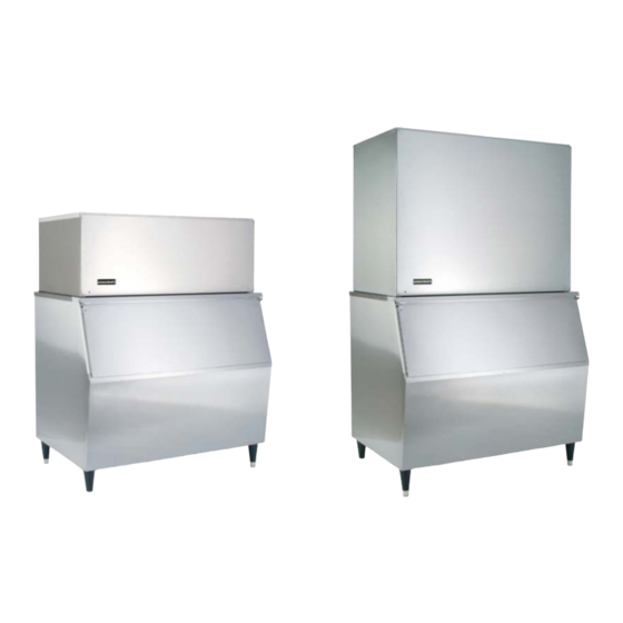
Ice Cube Makers - GT36x, GT56x, GB56x, GB106x
Stacking Instructions - Multiple GB56x or GB106x
Ice Cube Crushers - T27x
Pre-charged Remote Air-Cooled Condenser - RC214APV
GT36x
GT56x
GB56x
GB106x
KDIndustries, Inc.
1525 East Lake Road
Erie, PA 16511-1088 U.S.A.
(800) 840-9577
FAX: (800) 548-9392
www.kold-draft.com
November 2016
This manual is updated periodically. Visit http://www.kold-draft.com/resources/literature.php for the latest version.
- -
Advertisement
Table of Contents
Troubleshooting

Related Manuals for Kold-Draft GB1064LC


Summary of Contents for Kold-Draft GB1064LC
- Page 1 Ice Cube Crushers - T27x Pre-charged Remote Air-Cooled Condenser - RC214APV GT36x GT56x GB56x GB106x KDIndustries, Inc. 1525 East Lake Road Erie, PA 16511-1088 U.S.A. (800) 840-9577 FAX: (800) 548-9392 www.kold-draft.com November 2016 This manual is updated periodically. Visit http://www.kold-draft.com/resources/literature.php for the latest version.
- Page 2 KOLD-DRAFT Installation, Operation, Technical Service Specifications and Replacement Parts Manual Ice Cube Makers GT36x, GT56x GB56x, GB106x Stacking Instructions Multiple GB56x or Multiple GB106x Ice Cube Crushers T27x,T28x Pre-charged Remote Air-Cooled Condenser RC214APV (For GB106xR) Copyright 2015 KOLD DRAFT INTERNATIONAL Unauthorized reproduction of this manual is freely permitted for all purposes except for monetary gain.
-
Page 3: Table Of Contents
Table of Contents SAFETY INFORMATION ......................... 4 ICE MAKER IDENTIFICATION ......................2 Serial Number Plate Location ....................... 2 Date Code Key ..........................2 Model Number Key ........................3 ICE CUBER Installation ........................4 What’s in the box .......................... 4 Required Tools ..........................4 Pre-Install Checklist ........................ - Page 4 COMPRESSOR TEST PROCEDURE ................... 33 Test Procedure for a Short Circuit to Ground (Ground Fault) ............. 34 Test Procedure for Continuity And Proper Resistance ............... 34 Test Procedure for Compressor Electrical Components ............35 Testing The Run Capacitor: ......................35 Testing The Start Capacitor: .......................
-
Page 5: Safety Information
• Never operate equipment that has been altered from the original KOLD-DRAFT specifications. • Use of non-approved parts when servicing KOLD-DRAFT equipment will void the equipment warranty. Warning: Use only genuine KOLD-DRAFT replacement parts, Use of non-approved parts when servicing KOLD-DRAFT equipment may create a safety hazard, cause equipment damage, property damage and will void the warranty. -
Page 6: Ice Maker Identification
ICE MAKER IDENTIFICATION Serial Number Plate Location See the following for the location of the serial number plate. KDINDUSTRIES, INC. ERIE, PA. U.S.A. GB564AK 000000 208-230V/60HZ/1PH 30oz. R-404a Note: A complete model number and date code are essential for the accurate selection of replacement parts. -
Page 7: Model Number Key
Model Number Key Note: Model numbers mentioned in this manual that look like GB56x are used to refer to general families of machines. The “x” could stand for any combination of a machine’s electrical characteristics, condenser type and cube size Cube Size Full Cube Half Cube... -
Page 8: Ice Cuber Installation
Placing equipment in these locations will result in reduced capacities, high system pressures and may cause equipment failure. Note: Each Kold-Draft ice machine has successfully completed a quality assurance test and has been factory inspected before shipping. When receiving the unit please inspect it for physical damage. -
Page 9: Pre-Install Checklist
• All water lines have been purged before connection. • All KOLD-DRAFT models are intended to be installed with a permanent connection to the field electrical supply. Drop cord connections are not to be used with this equipment. Always be sure the power supply is the same as the ice machine’s electrical specification, which is listed... - Page 10 • Electrical service must fall within the voltage tolerances listed below: Nominal (V) No-Load Maximum Full-Load Minimum 115 (1 Series) 208-230 (4 and 5 Series) 230 (7 Series) 220/380 (8 Series) 420/3 phase 210/1 phase • Breaker or fuse service must be no greater than the maximum rating as specified on the rating label attached to the back of the machine.
-
Page 11: Additional Pre-Install Information For Cooling Tower Applications (L Models)
Additional Pre-install Information for Cooling Tower Applications (L models) The ice machine does not need to be modified for use with a cooling tower provided the cooling tower is properly designed for the application. Information regarding the amount of heat rejection, as well as the pressure drop through the condenser and liquid valves is required to properly select or design a cooling tower application for an ice machine. -
Page 12: Assembly
After installation, seal around the drain tube where it leaves the machine. Note: All KOLD-DRAFT bins will have a provision for the drain pan outlet tube to exit the rear of the bin. Ice machines that will be used on bins not manufactured by KOLD-DRAFT will require a drain riser adapter made by KOLD-DRAFT to allow sufficient clearance for the drain pan outlet tube to exit the back of the assembly. - Page 13 7. Make all plumbing and electrical connections to the ice machine and ice storage bin in accordance with local regulations. 8. Remove the strap securing the bin level probe and install through the bottom of the ice machine. Ice machines on top of other ice machines or ice crushers should have the bin probe stuck through the bottom of the machine directly above the bin.
-
Page 14: Initial Start Procedure
INITIAL START PROCEDURE 1. Be sure that the on-off switch is in the “off” position and the ice-clean switch is in the “clean” position. 2. Turn on the power and water supply and check all supply lines for leaks. 3. Make sure all pump and water tank hoses are connected, then pour 1/2 quart (1/2 liter) of clean potable water into the circulation system to lubricate and prime the pump(s). -
Page 15: Ice Machine Cleaning Procedure
ICE MACHINE CLEANING PROCEDURE It is recommended to perform this cleaning procedure at a minimum twice per year. Note: Use a clean plastic bottle fitted with a stopper or cap that has a pouring tube and a vent to facilitate mixing and pouring of the specified solutions. Mix 3 oz. -
Page 16: Specifications
SPECIFICATIONS Machine Capacities Capacity and Energy Input Ratings Water Use, gal/100# (l/kg) Lb (Kg) per 24hr Lb (Kg) per 24hr kWh/100# Model Number kWh/100# (kJ/kg) Potable Condenser Cubes per cycle (kJ/kg) 90/70 Ambient/Water 70/50 Ambient/Water GT361AC 216 (98) 7.95 (631) 270 (122.47) 5.96 (473) 22 (1.84) -
Page 17: Electrical Use And Machine Dimensions/Weight
Electrical Use and Machine Dimensions/Weight Amps Amps Dimensions - inches (cm) Ship Weight CA Power Model Number Min Circuit Ship Weight #(kg) Fuse/Breaker Tier GT361AC 30.1 (76.5) 25.7 (65.3) 16.9 (42.9) 180 (82) GT361AHK 30.1 (76.5) 25.7 (65.3) 16.9 (42.9) 180 (82) GT361LC 11.1... -
Page 18: Water Fill Levels, Cycle Times And Harvest Weights
Water Fill Levels, Cycle Times and Harvest Weights Model Group and Cube Type GB56x GB106x Water Fill Level inches (mm) * 2.75 (70) 2.75 (70) 2.75 (70) 2.75 (70) Approximate Cycle Time (Minutes) 7.70 7.10 15.40 14.20 Approximate Harvest Weight-lbs. (kg) (3.49) (3.22) (6.98) -
Page 19: Components
COMPONENTS Mechanical Components Refrigerant Compressor: Provided to pump refrigerant through the refrigeration system. See the serial number plate for refrigerant specification and electrical characteristics. Condenser: All air-cooled and liquid-cooled models are provided with a self-contained refrigerant condenser to remove heat from the refrigeration system. These condensers are designated in the model number as (“A”) air-cooled and (“L”) liquid-cooled. - Page 20 Water Pump: Continuously circulates the water from the water tank, through the water plate during the ice making cycle. The water pump also operates during the wash cycle to circulate cleaning and sanitizing solution. Actuator Motor: Rotates the cam arms counter-clockwise, at the beginning of the ice harvest cycle, to lower the water plate, so the ice can fall out of the evaporator.
- Page 21 Evaporator Temperature Probe: Senses the temperature of the evaporator. During the defrost cycle, the evaporator must warm sufficiently to release the ice. This probe signals the controller to terminate the defrost cycle, after the ice has fallen out of the evaporator, and start the next ice making cycle.
-
Page 22: Gb106X Series Unique Components
Plate Up Switch: This switch is actuated by the water plate and informs the controller about the position of the plate—fully up or not fully up. If this switch is not actuated when the water plate closes, because ice is remaining on the water plate surface, the actuator motor will reverse and reopen the water plate. -
Page 23: Controller
Controller Programming Port Machine Status Water Level Sensor Sequence Evaporator Temperature Reset Button Input Status Temperature Sensor Port Bin Full Adjustment Fault Codes Switch Input Port Water Rinse Jumper (Left) Dual Evaporator Factory Use Only Jumper (Right) AC Outputs Machine Status: Displays the position of the Ice/Clean switch or an Alarm. Sequence: Displays the current stage of the ice making process. (See Page 26 for more information) Input Status: Displays the status of the individual sensors for the ice making process. - Page 24 >40 Rev 1.1, 1.2, 1.3,1.4,1.5 I f the Freeze cycle lasts less than 5 minutes 3 times in a row before an automatic harvest the controller will shut down the ice maker and provide LED fault indicators. Rev 1.6 and higher After 3 consecutive occuerences of fault 40 the machine will attempt to remove any blockages by defrosting and cycling water –...
- Page 25 Stacked Jumpers: • Under normal operation all machines will have a jumper across the left pins. If this jumper is removed the water valve will stay energized to thoroughly rinse the water plate during the water plate lowering, harvest and water plate rising cycles. Note: The machine will need reset for the controller to acknowledge this change.
- Page 26 Bin Full Adjustment: To increase the temperature at which the ice level probe reacts to contact with ice in the bin turn the dial clockwise. To decrease, turn the dial counterclockwise. The temperature range for this adjustment is between 33 and 45F. Note: After adjustment the controller must be reset.
-
Page 28: Error-Code Troubleshooting
ERROR-CODE TROUBLESHOOTING - -Before troubleshooting, first check the Control Board and verify your software Revision Level (Rev. 1.1, 1.2, or 1.3) CODE: FAULT CODE INDICATES: POSSIBLE CAUSE: SOLUTION: (Rev. 1.1/1.2/ 1.3 ) 1) Bad Evaporator Probe (shorted) or wiring. 1) Repair/replace wiring or replace Probe. Evaporator temp over 120F 2) Hot Gas Valve stuck open - Cuber stuck in extended harvest 2) Pull down the Water Plate and verify that Hot Gas Valve mode. closes after the Water Plate closes. Repeat, with power to the 3) Bad Control Board Hot Gas Valve coil disconnected. If Hot Gas Valve does not 10> 4) Actuator Motor won't raise Water Plate. close, replace it. 3) Replace Control Board 4) Replace Actuator Motor. (Motor never raises Plate to actuate Plate Switch, so HGV stays open & Evap temp rises >120F. (Rev. 1.1) 1) Cam Arm or Cam Pin is broken. 1) Replace Cam Arm or Cam Pin. Water Plate failed to close 2) Cam Spring disengaged or broken. 2) Reinstall springs or replace as needed. 3) Plate-Up Switch stuck open or not actuating. 3) Adjust switch actuator or replace as needed. Check to insure after three consecutive 4) Over-freeze causing ice to stick on waterplate. that the Plate-Up Switch actuates before the Arms-Up Switch attempts. 5) Silicone coating on Waterplate worn away. actuates. 6) During harvest, the Evaporator Probe is out of adjustment 4) Lower the short water level probe, in 1/16" increments, until (Rev. 1.2 / 1.3) (reads too warm) or is defective. cubes have a pea-sized dimple in the center. - Page 29 ERROR-CODE TROUBLESHOOTING - -Before troubleshooting, first check the Control Board and verify your software Revision Level (Rev. 1.1, 1.2, or 1.3) CODE: FAULT CODE INDICATES: POSSIBLE CAUSE: SOLUTION: (Rev 1.1/1.2/1.3) 1) Slushing, in Pump, water lines or Water Tank, due to 1) Insure Expansion Valve (TXV) is covered with insulating foam. Freeze time less than 5 min., Expansion Valve mis-adjustment or not being wrapped in Adjust TXV as needed. As a starting point, gently turn the TXV insulating foam, or failure. in CW direction until it stops, then turn it CCW 5-1/2 turns. for 3 consecutive times. 2) Low-level Probe circuit is open, or the Water- Level Probe Adjust in 1/4-turn increments as needed. Assy is bad. 2) Repair wiring to Low-Level Probe or replace Probe Assy. (Water level in the glass Probe Tube is 3) Water is being lost somewhere (leaking), causing premature 3) Inspect hoses, water tank, water pump, water plate and 40> prematurely falling below the low-level harvest to occur. water level probe assembly to locate leak. Repair or replace probe, during the first 5 minutes of the 4) During harvest, Evaporator Probe out of adjustment (too part as needed. freeze cycle, or, the Low-level probe warm). 4) Adjust colder (CW) circuit is open) 5) High-level Probe possibly short circuiting during fill, causing 5) Locate & repair short circuit. short fill and hollow cubes. 1) Evaporator Temperature Probe out of adjustment (reads too 1) On the Controller, adjust Evaporator Probe pot CW, to a Rev 1.1 / 1.2 / 1.3 warm), or is defective (open). colder setting, so that the Water Plate returns to the closed Harvest cycle exceeds 20 min.
- Page 30 ERROR-CODE TROUBLESHOOTING - -Before troubleshooting, first check the Control Board and verify your software Revision Level (Rev. 1.1, 1.2, or 1.3) CODE: FAULT CODE INDICATES: POSSIBLE CAUSE: SOLUTION: (Rev 1.1/1.2) 1) Water supply off or major leak in the water tank, or water 1) Turn on water supply or check for leaks. Water fill exceeds 5 min. lines. 2) Replace, bypass or eliminate external water filter. 2) External water filter plugged. 3) Place in Wash Mode and pull down on water plate, to lower 3) Water solenoid valve inoperative. it. On return up, water valve will energize to fill, until the short (Rev 1.3) 60> 4) Upper (short) Probe, in the Water-Level Probe Assy, may have probe is reached. If water solenoid valve has power & water, Water fill exceeds 3 min, a loose wire connection (open). but does not open, replace the valve. then the Valve closes & waits 10 minutes, 5) Common (longest) Probe, in the Water-Level Probe Assy, may 4) Verify wire connection is securely crimped on top of probe & as Code 60 LED flashes. Valve then opens have a loose connection (open). back to Controller. & tries again. This routine repeats 3X 6) Controller is bad. 5) Verify wire connection is securely crimped on top of probe & and results in a solid Code 60, if the fill is back to Controller. not completed on the third try. 6) Replace Controller. (Rev 1.1/1.2) (Rev 1.1/1.2) 1) No action required. (Increase incoming water temp to > 45F 1) This is not necessarily a fault condition, but could indicate for best results) Evaporator Temperature < 31F,...
-
Page 31: Sequence Of Operation
SEQUENCE OF OPERATION The following tables describe the general states and sequence of operation for the ice machine models in ice-making mode with an additional table depicting the status when the ice bin is full and the cleaning mode. The charts provide information about the inputs to the controller and the corresponding AC outputs associated with each part of the ice making cycle. -
Page 32: Ice Bin Full/Cleaning Mode
Ice Bin Full/Cleaning Mode Cleaning Ice Bin Full Mode Control Status Status Bin Level Probe Cold/Bin Full Warm or cold Ice-Clean Switch Clean Contactor Open Open Water Plate Switch Up or Down Evaporator Temperature Probe Warm or Cold Warm Water Level Control Low or High High* Arms-Up/Down Switches... -
Page 33: Lower
control stream or from the water tank during the freeze cycle. The water level in the liquid level probe tube must get below the level of the low water level probe initiate the harvest cycle. If there is an excess of water in the water tank, the water pump outlet pressure increases when the evaporator cells are full, and the control stream rises and flows over the dam to the drain pan to evacuate the liquid level control tube. -
Page 34: Start Methods
START METHODS Ice Making Mode Start Up At power up in the ice making mode the electronic control will monitor the following criteria: If the evaporator temperature is colder than the Harvest Termination temperature at start up the controller will switch to the Lower state. If there is an obstruction preventing the water plate from closing the Plate Up switch at startup, the controller will switch to the Lower state. -
Page 35: Gt36X, Gt56X, Gb56X Wiring Diagram
GT36X, GT56X, GB56X WIRING DIAGRAM Compressor Wiring GT361 Models Only GT36x, GT56x, GB56x... -
Page 36: Gb1064 A & L Wiring Diagram
GB1064 A & L WIRING DIAGRAM Note: A wiring diagram for remote condenser models (GB106xR) is on the following page. Compressor Wiring . 06.01.16.docx - 31 – new 60 Series Service Manual.rev... -
Page 37: Gb106Xr Wiring Diagram
GB106XR WIRING DIAGRAM... -
Page 38: Compressor Test Procedure
• Never modify the circuitry of KOLD-DRAFT equipment from the original specifications. • Use only genuine KOLD-DRAFT replacement parts. • Use of non-approved parts when servicing KOLD-DRAFT equipment may create a safety hazard or cause equipment and property damage. • Use of non-approved parts, when servicing KOLD-DRAFT equipment, will void the equipment warranty. -
Page 39: Test Procedure For A Short Circuit To Ground (Ground Fault)
Test Procedure for a Short Circuit to Ground (Ground Fault) 1. Disconnect all electrical power to the system, making sure all power legs are open. 2. Remove the protective terminal cover. Inspect for evidence of overheating at any connection. Overheating is an indication that a compressor motor problem exists. Disconnect all leads from the terminal pins. -
Page 40: Test Procedure For Compressor Electrical Components
Test Procedure for Compressor Electrical Components 1. Testing The Potential Relay: 2. Before testing the relay, be sure it is the one specified for use with the ice machine compressor and the mounting position of the relay is correct. 3. Measure for continuity between terminals 5 and 2—if there is no continuity, replace the relay. 4. -
Page 41: Additional Service Information
Additional Service Information • Testing the External Thermal Protector: • After allowing sufficient time for the thermal protector to reset, disconnect it and test for continuity across the terminals. If there is no continuity, replace the thermal protector. • Disconnect and test the compressor wiring by confirming that there is continuity between relay terminal 5 and compressor terminal C and also between terminals 2 and S as well as 4 and R. -
Page 42: Water Plate Replacement
WATER PLATE REPLACEMENT 1. Turn off water and open plate until cams are in the 9:00 position then turn off the power. 2. Remove the control stream drain hose. 3. Remove water level probe assembly by sliding it to the right beyond the control stream box and lift. -
Page 43: Water Plate Alignment
WATER PLATE ALIGNMENT If the water plate is not aligned with the evaporator, the cubes may appear cloudy or misshapen. Dimension “A” is not adjustable. If this dimension is out of tolerance, the evaporator or water plate mounting components may be damaged. Adjustments to dimension “B”... -
Page 44: Water Plate Up/Down Position And Adjustment
WATER PLATE UP/DOWN POSITION AND ADJUSTMENT When the water plate is up (closed), the spring end of the cam arm must be in the 12 o’clock position, with the spring on the left side of the cam arm hub. The arms up switch lever (front) will be down and the arms down switch lever (back) will be up. - Page 45 ACTUATOR MOTOR ELECTRICAL TESTS The following tests are for troubleshooting the actuator motor and related circuits: Use an AC voltmeter set for the proper range. Voltages in the tables are measure across the motor reversing capacitor (between the colored motor lead wires. If there is no ice in the evaporator(s) and the water plate(s) is (are) not fully closed (with the water plate switch(es) pushed up and the “ARMS UP”...
-
Page 46: Probe Test Procedure
PROBE TEST PROCEDURE Water Level Probes: Water level probes can be tested at any temperature and are good if they exhibit continuity (0 ohms resistance) along the length, between the probe wire and the connector at the controller. It is advisable to flex the probe at the two connections, while testing for continuity, to eliminate the possibility of an intermittent failure. - Page 47 FOR GB1064 MACHINES BUILT BEFORE 607945 WATER FILL ADJUSTMENT INSTRUCTIONS Note: This applies only for GB1064 machines with serial numbers before 607945. Machines built after 607945 have an upgraded water valve which equalizes the amount of water in each tank per load. Since supply pressures vary between the factory and install locations, water fill levels between the top and bottom water tanks will also vary.
- Page 48 . 06.01.16.docx - 43 – new 60 Series Service Manual.rev...
-
Page 49: Troubleshooting
TROUBLE SHOOTING Problem Possible Cause Solution On-Off switch in "Off" position Move switch to "On" position. No power at ice machine. Circuit Replace fuse or reset breaker. protector open. Check circuit for overload condition. Ice machine off because bin is full of Use ice or move ice away from bin Ice machine is not ice. - Page 50 TROUBLE SHOOTING Problem Possible Cause Solution Replace compressor. See Compressor is defective. compressor test procedure for more information. Condenser fan Replace motor if it does not run motor is not Fan motor protector open. when cool or at normal operating operating on air- conditions.
- Page 51 TROUBLE SHOOTING Problem Possible Cause Solution Evaporator temperature probe is defective and not sensing warm Test probe and replace if defective. evaporator temperature. Actuator motor output shaft is tuning Cam pin is broken or missing. but front cam is not turning. Inspect operation of arms up and Actuator motor will not run.
- Page 52 TROUBLE SHOOTING Problem Possible Cause Solution The water supply pressure must be a minimum of 5 PSI (34 kPa) dynamic at the water valve. Be sure that the supply line is of adequate size. This is especially important for liquid cooled models Slow water fill.
- Page 53 TROUBLE SHOOTING Problem Possible Cause Solution Disassemble and clean water valve No voltage measured at water valve if needed. Make sure the bleed coil. Water valve remains open holes in the valve diaphragm are because of dirty or defective water open.
- Page 54 TROUBLE SHOOTING Problem Possible Cause Solution Adjust spacing between evaporator Ice cubes do not break apart after and water plate. See the web defrost because of thick web between thickness adjustment illustration for cubes. more information. Ice cubes have uneven dimples. Dimples are larger on right side of Remove refrigerant and recharge evaporator because of low refrigerant...
-
Page 55: Parts Diagrams
PARTS DIAGRAMS GT36x Parts – Left Side 5-Spring (2x) 6-Front Cam w/Springs 4-Evap/Bin Temp Sensor Assembly 2-Evaporator 7-Rear Cam w/Springs 9-High Pressure Cut-Out 3-Plate/Cam Switch (3x) 8-Actuator Motor 1-Water Plate 20-Filter Drier 10-Ice/Clean Switch 19-Expansion Valve 18-Probe Tube Assy 11-Controller 12-Water Deflector 17-Water Pump 13-Fuse Holder w/ 4A fuse... - Page 56 GT36x Parts – Right Side-Air Cooled 5-Fan Blade 6-Fan Motor 7-Condenser (Air Coole ) Description Model Part No. Defrost Valve Coil GT361 102101101 Defrost Valve Coil GT364 102101201 Defrost Valve Body GT36x 102100801 Compressor GT361 102140701 GT36x Parts – Right Side-Liquid Cooled Compressor GT364 102141701...
-
Page 57: Gt56X Parts
GT56x Parts – Left Side 4-Evap/Bin Temp Sensor Assembly 8-Actuator Motor 5-Front Cam w/Springs 3-Plate/Cam Switch (3x) 6-Rear Cam w/Springs 1-Water Plate 2-Evaporator 7-Spring (2x) 9-High Pressure Cut-Out 24-Filter Drier 23-Expansion Valve 10-Water Deflector 22-Probe Tube Assembly 21-Water Tank 11-Defrost Valve Coil 20-Water Pump 19-Drain Pan 12-Ice/Clean Switch... - Page 58 Defrost Valve Coil GT564 102101201 GT56x Parts -Right Side Water valve in same location on “A” and “L” models. 1-Water Valve Left Side 2-Defrost Valve Coil Liquid Cooled 3-Defrost Valve Body 4-Liquid Regulator Valve 5-Condenser (Liquid Cooled) 6-Condenser (Air Cooled) Description Model(s) Part No.
- Page 59 GB56x 2-Evaporator 3-Evap/Bin Temp Sensor Assembly 1-Water Plate 5-Actuator Motor 4-Plate/Cam Switch (3x) 21-Probe Tube Assembly 6-High Pressure Cut-Out 20-Filter Drier 7-Defrost Valve Coil 19-Expansion Valve 8-Ice/Clean Switch 9-Controller 18-Water Pump 12-Front Cam w/Springs 10-Fuse Holder with 4A fuse 15-Spring (2x) 17-Drain Pan 13-Rear Cam w/Springs 16-Water Tank...
- Page 60 GB56x-Air Cooled 1-Defrost Valve Coil 4-Water Valve 5-Fan Blade Blade 6-Fan Motor 2-Defrost Valve Body 7A-Condenser 3-Compressor (Air Cooled) GB56x-Liquid Cooled Description Model(s) Part No. Defrost Valve Coil GB561 102101101 8-Liquid Regulator Valve 4-Water Valve Defrost Valve Coil GB564 102101201 Defrost Valve Body GB56x 102101001...
-
Page 61: Gb106X Parts
GB1064X Parts 3-Plate/Cam Switch 4-Actuator Motor 2-Evaporator 1-Water Plate 5-Defrost Valve Coil 26-Filter Drier 6-Defrost Valve Body 25-Expansion Valve 7-Defrost Valve Coil 19-Water Pump 23-Drain Pan 8-High Pressure Cut-Out 22-Probe Tube Assembly 9-Defrost Valve Body 21- Filter Drier 10-Ice/Clean Switch 20-Expansion Valve 11-Controller 12-Fuse Holder... - Page 62 GB1064R Side 1-Harvest Regulator Valve 7-Head Pressure Control Valve 2-Water Valve 3-Liquid Line Solenoid Valve Body 6-Compressor 4-Liquid Line Solenoid Valve Coil 5-Receiver Description Model(s) Part No. Harvest Regulator Valve GB106xR 102122001 Water Valve – S/N Before 607945 GB1064 102139101 Water Valve –...
- Page 63 GB1064A Side 1-Defrost 3-Fan Motor 4-Fan Blade Valve Coil Error! Referenc e source found. 8- Condenser-Air Cooled 2-Defrost Valve Body 1-Defrost Valve Coil 2-Defrost Valve Body 6-Compressor 5-Water Valve Description Model(s) Part No. Defrost Valve Coil GB1064A 102101201 GB1064L Side Defrost Valve Coil GB1064L 102101101...
-
Page 64: Parts List
PARTS LIST Description Model(s) Part Number Actuator Motor GT361 102140901 Actuator Motor GT561, GB561 102123801 Actuator Motor GT364, GT564, GB564, GB1064 102123802 Actuator Motor Box Cover GT36x 102143401 Actuator Motor Box Cover GT56x, GB56x, GB106x 102137201 Actuator Motor Capacitor GT361, GT561, GB561 102124101 Actuator Motor Capacitor GT364, GT564, GB564, GB1064... - Page 65 Description Model(s) Part Number Evaporator "C" GT56x, GB56x, GB106x 102144501 Evaporator "HK" GT56x, GB56x, GB106x 102144601 Evaporator Shim Set GBR00111 Evaporator Spacer Set “ C” “HK” GBR00113 Expansion Valve GT36x 102118802 Expansion Valve GT56x, GB56x, GB106x GBR02359 Fan Blade GT36x, GT56x, GB56x, GB106x 102101602 Fan Motor GT361, GT561, GB561...
- Page 66 Description Model(s) Part Number Spring Boss GBR00951 Stacking Chute GB106x 102139601 Start Capacitor GT561, GB561 102119508 Start Capacitor GT564, GB564 102119502 Evaporator Shim Set GBR00111 Evaporator Spacer Set GBR00113 Start Capacitor GB1064 102119509 Start Relay GT561, GB561 102104709 Start Relay GT564, GB564 102104706 Start Relay...
-
Page 67: Actuator Motor Kit Application List
ACTUATOR MOTOR KIT APPLICATION LIST 102129202 102123802 102123902 206121201 102129201 102123801 102123901 102124001 Model Number 208/240V 208/240V 208/230V 115V 60HZ 115V 60HZ 115V 60HZ 115V Timer Kit Motor Cover Kit 50/60HZ 50/60HZ Timer Kit Energy Efficient GT361 GB561, GT561 GB564, GT364 GB1064 2-Required Classic... -
Page 68: Stacking Instructions
• Instruct all personnel in the proper use of the equipment. • Clean up any spillage immediately. • Failure to comply with all KOLD-DRAFT installation guidelines may cause personal injury, equipment or property damage and may void the product warranty. - Page 69 5. Apply the gasket provided to the top of the lower ice machine frame as shown. Place the gasket over the frame spacers to secure them in position. 6. Position the stacking chute in the lower machine as shown. Locate on the support channels, against the partition wall.
- Page 70 8. Replace the front and back deflectors of the top ice machine with the deflectors provided in the stacking kit. Install the deflectors into the slots in the back wall and front rail. Push down on the deflectors until they engage beside the stacking chute and snap in place. 9.
-
Page 71: Ice Cube Crushers - T27X
ICE CUBE CRUSHERS - T27X (For KOLD-DRAFT GB series Ice Makers) Installation, Operation, Technical Service and Replacement Parts... -
Page 72: Ice Crusher Safety Information
• Warn all users to clean up spillage immediately, keep storage bin doors closed, and report any apparent leakage or unusual sounds to maintenance personnel. ® • Proper installation must include KOLD-DRAFT GB Series Ice maker mounted above Crusher. . 06.01.16.docx - 67 –... -
Page 73: Ice Crusher Installation
Pre-Install Checklist • All KOLD-DRAFT models are intended to be installed with a permanent connection to the field electrical supply. Drop cord connections are not to be used with this equipment. Always be sure the power supply is the same as the ice machine’s electrical specification which is listed... -
Page 74: Assembly/Installation
DANGER: Failure to comply with these regulations may cause serious injury or death and cause damage to the machine and its surroundings. Assembly/Installation 1. Position the ice storage bin maintaining the minimum clearances specified in the ice maker instructions. 2. Level the bin with adjusters on its legs, or by shimming if the bin is to be sealed to the floor. If there are gaps between the bin and the floor greater than 1/8 inch, install a cove molding around the bin bottom. - Page 75 Note: The plastic selector knob must be removed before the front cover can be removed on older machines. 8. Insert the straight thermostat holder tube into the rubber grommet located directly behind the crusher motor. Route the crushed ice thermostat capillary tube through the straight thermostat tube holder.
- Page 76 Notes: ® • The crusher is designed to operate in conjunction with one or two KOLD-DRAFT makers. Two motor control relay blocks are provided and a relay coil must be installed for each ice maker used. Each relay coil must have a voltage rating matching the voltage of the ice maker, regardless of the crusher motor voltage.
- Page 77 16. Connect piggyback terminals of the motor control wire assembly to the tabs of the hot gas valve on the ice maker. 17. Reconnect the white plug assembly to the piggyback terminals of the motor control wire assembly as shown below. 18.
-
Page 78: Initial Start-Up
23. Turn off the breaker or disconnect the fuse that will service the machine. 24. Make all electrical connections to the electrical service in a manner that complies with local code Note: • If two separate ice making machines (for example two GB1064 models stacked) are installed the bin thermostats of both ice makers will need to be connected to the crusher. -
Page 79: Ice Crusher Cleaning Procedure
ICE CRUSHER CLEANING PROCEDURE DANGER: • Disconnect or turn off all ice machine and crusher fuses or breakers before cleaning either machine. • Do not use ammonia solutions or strong detergents in cleaning the crusher. • Never use appliance polishes, finish preservatives or cleaners in areas that could contact ice. Warning: •... -
Page 80: Wiring Diagram
WIRING DIAGRAM . 06.01.16.docx - 75 – new 60 Series Service Manual.rev... -
Page 81: Pre-Charged Remote Air Cooled Condenser
PRE-CHARGED REMOTE AIR-COOLED CONDENSER - RC214APV Installation, Operation, Technical Service and Replacement Parts PARTS FOR CONDENSER 102140601 FAN MOTOR-RC214APV-230V GBR01890 1/2 MALE SELF SEAL COUPLING FOR CONDENSER / ICE MAKER GBR01889 3/8 MALE SELF-SEALING COUPLING FOR CONDENSER / ICE MAKER PARTS FOR LINE SET GBR02218 1/2 FEMALE SELF SEAL COUPLING FOR LINE SET GBR02219 3/8 FEMALE SELF-SEALING COUPLING FOR LINE SET... -
Page 82: Pre-Charged Remote Air Cooled Installation
• Never operate this equipment with covers, panels, guards or other parts removed or not properly secured. • KOLD-DRAFT reserves the right to disallow any warranty claims which result from the use of non KOLD-DRAFT condensers and/or line sets. • Read the entire manual before installing, operating or servicing the machine. -
Page 83: Installation
• Avoid placing the condenser in the exhaust air stream of other equipment or within a distance equal to the width of the condenser from a wall or another piece of equipment. Stay away from kitchen exhaust fans to prevent grease accumulation on the fins. Use a curb, which extends above the deepest expected pond in the condenser area of the roof. -
Page 84: Minimum Total Charge Required
Minimum Total Charge Required Note: • The factory charge in dual-evaporator models is 168 oz (10.5 lb) R-404a. • The maximum total system charge for dual-evaporators is 208 oz (13 lb) R-404a. • The basic charge for a dual-evaporator model is 3 lb R-404a. To determine the total charge, add the following to the basic charge below: 1. -
Page 85: Electrical Information
Electrical Information Removing From Service When the ice maker is determined to be no longer useable please be sure that it is rendered safe for storage or disposal. All applicable recycling measures should be exercised to avoid injury and harm to the environment. The manufacturer and/or seller is not responsible for any harm to people, animals, property, and the environment caused by incorrect installation and/or disposal.
Need help?
Do you have a question about the GB1064LC and is the answer not in the manual?
Questions and answers