Table of Contents
Advertisement
Quick Links
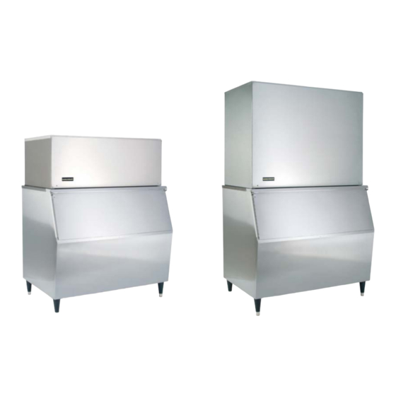
Installation and Operation
Manual for Kold-Draft
Products
ALL MODELS ARE INTENDED FOR INDOOR USE ONLY. DO NOT
INSTALL THE EQUIPMENT IN UNPROTECTED OUTDOOR AREAS.
DO NOT INSTALL THE EQUIPMENT IN WET AREAS.
GT36X, GT56X, GB56X, GB106X, T28X, AKD125, RC214,
RC314
KOLD-DRAFT
1525
E ast
L ake
R oad
Erie,
P A
1 6511-‐1088
U .S.A.
814-‐453-‐6761
FAX:
8 14-‐455-‐6336
www.kold-‐draft.com
Advertisement
Table of Contents


Need help?
Do you have a question about the GT36 Series and is the answer not in the manual?
Questions and answers