Table of Contents
Advertisement
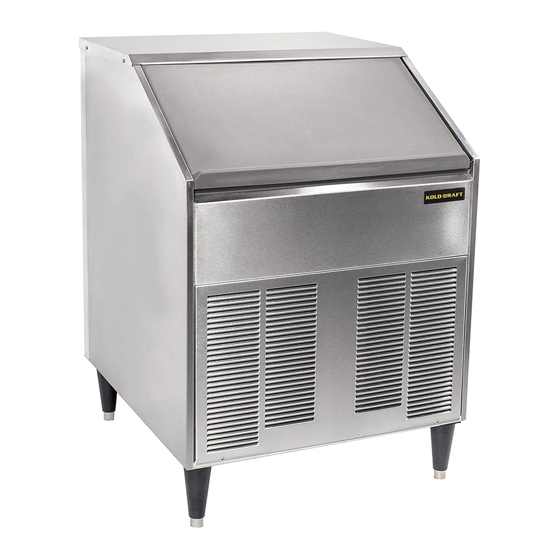
SC200 Series Ice Machine
Installation & OperationManual
Kold-Draft International, LLC
1525 East Lake Road
Erie, PA 16511-1088 U.S.A.
Phone: (800) 840-9577
Fax: (800) 548-9392
www.kold-draft.com
This manual is updated periodically. Visit http://www.kold-draft.com/resources/literature.php for the latest version.
Advertisement
Table of Contents

Subscribe to Our Youtube Channel
Related Manuals for Kold-Draft SC200 Series


Summary of Contents for Kold-Draft SC200 Series
- Page 1 SC200 Series Ice Machine Installation & OperationManual Kold-Draft International, LLC 1525 East Lake Road Erie, PA 16511-1088 U.S.A. Phone: (800) 840-9577 Fax: (800) 548-9392 www.kold-draft.com This manual is updated periodically. Visit http://www.kold-draft.com/resources/literature.php for the latest version.
- Page 2 KOLD-DRAFT INTERNATIONAL, LLC A DIVISION OF THE LEGACY COMPANIES, LLC Installation & Operation Manual SC200 Series Ice Machine Copyright2016 KOLD-DRAFT INTERNATIONAL, LLC Unauthorized reproduction of this manual is freely permitted for all purposes except for monetary gain. It is not guaranteed that this service manual is up to date, technically correct, complete, or free from writing problems or that the product is free from minor flaws or that it meets the needs of the customer.
-
Page 3: Table Of Contents
Table of Contents Section 1 General Information Safety Information ......Model Number Key . -
Page 4: Safety Information
Contact the freight carrier immediately to report any damage and file a claim. Have carrier note the damage on the bill of lading. Call Kold-Draft with your claim number to arrange replacement or repair. •... -
Page 5: Model Number Key
Ice Maker Identification Model Number Key Cube Size C = Full Cube HK = Half Cube K = Cube-Let Condenser Type A = Air cooled condenser-self contained L = Liquid cooled condenser-self contained Electrical Characteristics 1 = 115 volt-60 hz.-1ph. (2-wire plus ground) 4 = 208/230 volt-60 hz.-1ph. -
Page 6: Unpacking
Unpacking Unpacking a KOLD-DRAFT machine can be done by prying off the boards that are holding the cardboard box to the shipping pallet. The box can then be lifted vertically to expose the machine. Remove all packaging materials from the ice machine and protective film from the stainless steel surfaces. -
Page 7: Installation Requirements
Installation Requirements • The ice machine must be installed indoors and the location should be free of airborne contaminates including any corrosive elements. • Ambient air temperatures at the install location must be between 45°F (7°C) and 90°F (32°C).Ambient temperatures higher than the maximum specification will result in reduced capacities and high system pressures in air-cooled models. -
Page 8: Plumbing
Plumbing • The drain hose or pipe must not be reduced in size from the machine to the drain. The building drain must be able to accommodate all the drain water from the ice machine operation. • Individual drains will not be directly connected to a common manifold, drain or standpipe. If individual drains are to be discharged into a common manifold, drain or standpipe, a minimum 1.5”... -
Page 9: Electrical
Switching the machine “off” does not de-energize all circuits. Always disconnect power before servicing. • All KOLD-DRAFT models are intended to be installed with a permanent connection to the field electrical supply. See rating plate on the back of the machine for power supply requirements. -
Page 10: Operation
Operation Initial Start Procedure 1. Be sure that the on-off switch is in the “off” position and the ice-clean switch is in the “ice” position. 2. Make sure all water lines and hoses are securely connected, turn on water supply and check for leaks. -
Page 11: Controls And Adjustments
Controls and Adjustments On-Off Switch: Used to turn the ice machine on or off. CAUTION: Switching the machine “off” does not de-energize all circuits. Always disconnect power before servicing. Ice-Clean Switch:The “Ice” position signals the controller to provide full operation of the ice machine. -
Page 12: Sequence Of Operation
Sequence of Operation The following tables describe the general states and sequence of operation for the ice machine models in ice-making mode with an additional table depicting the status when the ice bin is full and the cleaning mode. The charts provide information about the inputs to the controller and the corresponding AC outputs associated with each part of the ice making cycle. -
Page 13: Description Of Each Process
Sequence of Operation Description of Each Process The following sequence begins with the cuber as shipped from the factory with the water plate(s) closed and ready to begin a normal ice making cycle. Fill:The water solenoid valve will be energized until the water level switch indicates that the sump is full. - Page 14 Water Plate Closure Problems:If the water plate is not able to close due to ice remaining on the water plate surface, the plate will reopen until it is clear. Shutdown-High Pressure:All models are provided with a high pressure cutoff, which interrupts power to the compressor and to the condenser fan motor, if so equipped, when the high-side pressure rises to the cutoff setting.
-
Page 15: Cleaning Procedure
Move the Ice-Clean Switch to the “Clean” position and turn the ice machine on. 2. While the water plate is filling pour 3 fl. oz. (90 mL) of Kold-Draft nickel-safe ice machine cleaner (Kold-Draft part no. 500023) into the water sump though the opening along its front edge. -
Page 16: Cleaning Mode Start-Up
Cleaning Mode Start Up At power up in the wash mode the electronic control will monitor the following criteria: If the water plate is not in the full up (closed) position at start up, the controller will close the plate. If there is ice on the surface of the water plate, preventing it from closing, the controller will reopen the plate to clear it. -
Page 17: Wiring Diagram
Wiring Diagram SC200 Installation& Operation Manual 3-16... -
Page 18: Problems And Solutions
Problems and Solutions PROBLEM POSSIBLE CAUSE SOLUTION On-Off switch in "Off" position Move switch to "On" position. No power at ice machine. Circuit Reset breaker. Check circuit for protector open. overload condition. Use ice or move ice away from bin Ice machine is not Ice machine off because bin is full of ice. - Page 19 Problems and Solutions PROBLEM POSSIBLE CAUSE SOLUTION Connection between actuator motor Actuator motor output shaft is turning but shaft and right side operator broken. front cam is not turning. Check set screw, tighten or replace. Water plate will not close after defrost.
- Page 20 Problems and Solutions PROBLEM POSSIBLE CAUSE SOLUTION No voltage measured at water valve coil Float switch defective. at fill cycle. Water valve will not open. Potable water level never reaches the high water Check for line voltage at controller Float switch OK but no voltage measured level during the fill cycle.
- Page 21 102148101 SC200 EVAPORATOR KIT-C CUBE Quantity per Description SC EVAPORATOR ASSEMBLY C-CUBE SC TXV BULB CLIP SCREW #8-32 X 5/8 PH PAN HD SS 10-32 THREADED STANDOFF - 7/16 OD x 15/16 L DELRIN SCREW - #10-32 X 1/2 HX HD CAP SC200 Installation&...
- Page 22 CONTROL BOX ASSY Description 102103701 RELAY-PLUG-IN DPDT 115VAC 102100701 SOCKET - IDEC #SH2B-02 510110601 ROCKER SWITCH SPST QUICK CONNECT 102145903 CONTROL PCB SC200 102145701 TEMP PROBE 55" PCB 1.8 SC HARVEST ASSIST SWITCH PUSH 510127701 BUTTON SC200 Installation& Operation Manual 3-16...
- Page 23 102148301 SC200 FAN ASSY .KIT Qty per Description 6.0000 SCREW-#8-18 X 1/2 PH PAN SS 4.0000 LOCKNUT-8-32 SS W/NYLON INSERT 1.0000 SC FAN MOTOR - 115V & 230V 1550 RPM CCW & CW SC FAN BLADE - PLASTIC 200 MM DIA. 28 DEGREE 1.0000 PITCH SC FAN BLADE WALL RING - PLASTIC 200 MM DIA.
- Page 24 PARTS LIST SC200 WATER PLATE & OPERATION ASSEMBLY DOC# 307108601 ITEM PART NUMBER QTY. DESCRIPTION 202115201 SC ROCKER PLATE ASSEMBLY- LEFT-SS 202115202 SC ROCKER PLATE ASSEMBLY RIGHT - SS 301176901 SC WATER PLATE SUPPORT 301184001 SC WATER PLATE COVER 301184201 SC WATER PLATE DEFLECTOR 503100319 SCREW #8-32 x 3/8 PH PAN MS SS...
- Page 25 504104501 DUMP VALVE 504103601 WATER VALVE 210113001 DUMP/WATER VALVE ASSEM. 102148301 FAN ASSEMBLY 516103001 FAN MOTOR 516103101 FAN BLADE 210113301 INLET TUBE ASSEM. 518103301 COMPRESSOR 102151601 START CAP. 102151602 RELAY 102151603 OVERLOAD 301184201 WATER PLATE DEFLECTOR 102148601 ACTUATOR MOTOR W/MAGNETIC SWITCHES & CPACITOR 301126101 ELECTRICAL INLET BOX COVER 516103301...
- Page 26 SC200 Installation& Operation Manual 3-16...
Need help?
Do you have a question about the SC200 Series and is the answer not in the manual?
Questions and answers