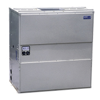
Summary of Contents for Carrier 50BL Series
- Page 1 §Ÿ à ¡ ◊ Õ °“√µ‘ ¥ µ— È ß ‡§√◊ Ë Õ ßª√— ∫ Õ“°“» ·§‡√’ ¬ √å Single-Package Cooling Units 50BY, BL 50BY, BL...
-
Page 3: Table Of Contents
Contents Safety Considerations................................4 Danger ......................................4 Warning ...................................... 4 Installation ....................................5-6 Air Duct Connection ................................. 6 Electrical Wiring ..................................7 Start-Up ....................................7-8 Maintenance and Service ..............................8-11 Troubleshooting ..................................12 Technical Specification ................................13 Unit Dimensions................................. 14-16 Electrical Data ..................................16 Electrical Wiring Diagrams ............................ -
Page 4: Safety Considerations
Safety Considerations The 50BY, BL Single-Package Cooling Units are designed to provide safe and reliable when operated within design specifications. However, due to system pressures, electrical components and equipment location, some aspects of installation, start-up and servicing of this equipment can be hazardous. Only trained, qualified installers and service mechanics should install, start up and service this equipment. -
Page 5: Installation
Receiving Unit - Check unit against shipping order. Inspect carefully fan concealed shipping damage. If shipment is damage or incomplete, file claim with transportation company and advise Carrier immediately. Location for Installation - Check the following when selecting a location to install unit: 1. -
Page 6: Air Duct Connection
CAUTIONS: 1. Do not connect supply line to condenser water outlet and return line to inlet. 2. Be sure to install water drain valve on piping. 3. Be sure to install pump on supply line, not return. 4. On city or waste water systems, install strainer to remove foreign matters. 5. -
Page 7: Electrical Wiring
Electrical Wiring Electrical Data - All wiring must comply with local electrical code requirement. All 50BY, BL units are completely wired internally at factory for voltage shown on the nameplate. Check the available power supply with the ± nameplate information. Voltage at the unit, with the unit operating must be within 10% of the voltage indicated on the nameplate. -
Page 8: Maintenance And Service
Oil Change - Level should be between 1/8 to 3/8 of sight glass on all 50BY(015-040), BL(050-080) units. Add Carrier approved oil, if necessary. §Ÿ à ¡ ◊ Õ °“√µ‘ ¥ µ— È ß ‡§√◊ Ë Õ ßª√— ∫ Õ“°“» ·§‡√’ ¬ √å... - Page 9 Pumpdown Procedure - when shutting down unit for an extended period of time, it is recommendable to pump down unit and store refrigerant in condenser. 1. Frontseat (close) liquid line shutoff valve. 2. Start compressor and run until low-pressure switch cuts out. 3.
- Page 10 To Alignment Fan and Motor Pulleys Loosen fan pulley set screws and slide fan pulley along fan shaft. Make angular alignment by loosening motor from mounting plate. Check alignment with a straight edge. §Ÿ à ¡ ◊ Õ °“√µ‘ ¥ µ— È ß ‡§√◊ Ë Õ ßª√— ∫ Õ“°“» ·§‡√’ ¬ √å...
- Page 11 To Adjust Belt Tension 1. Loosen four motor hold-down bolts and slide motor to tighten belts. 2. Adjust belt(s) so they can be depressed 30 mm. with one finger midway between pulleys. §Ÿ à ¡ ◊ Õ °“√µ‘ ¥ µ— È ß ‡§√◊ Ë Õ ßª√— ∫ Õ“°“» ·§‡√’ ¬ √å...
-
Page 12: Troubleshooting
Troubleshooting SYMPTOMS PROBABLE CAUSE REMEDY Power indicator light off Power switch off Turn switch on Blower fuse Replace Power indicator light on Fan belt broken Replace Low line voltage Check and correct cause Overload open Check and correct Overload indication light on Fan belt broken Replace Low line voltage... -
Page 13: Technical Specification
Technical Specification §Ÿ à ¡ ◊ Õ °“√µ‘ ¥ µ— È ß ‡§√◊ Ë Õ ßª√— ∫ Õ“°“» ·§‡√’ ¬ √å... -
Page 14: Unit Dimensions
Unit Dimensions 50BY008, 010 50BY015, 020 §Ÿ à ¡ ◊ Õ °“√µ‘ ¥ µ— È ß ‡§√◊ Ë Õ ßª√— ∫ Õ“°“» ·§‡√’ ¬ √å... - Page 15 Unit Dimensions 50BY025, 030 50BY040 §Ÿ à ¡ ◊ Õ °“√µ‘ ¥ µ— È ß ‡§√◊ Ë Õ ßª√— ∫ Õ“°“» ·§‡√’ ¬ √å...
-
Page 16: Electrical Data
Unit Dimensions 50BL050, 060, 080 Electrical Data Voltage Range Compressor No: 1 Indoor Fan Motor Power Supply Model Vols/Ph/Hz MIN. CKT AMIPS MOCP AMPS 50BY008 380/3/50 13.5 0.75 24.4 35.7 50BY010 380/3/50 17.7 1.50 29.2 49.2 50BY015 380/3/50 29.0 2.20 40.8 69.8 50BY020... -
Page 17: Electrical Wiring Diagrams
§Ÿ à ¡ ◊ Õ °“√µ‘ ¥ µ— È ß ‡§√◊ Ë Õ ßª√— ∫ Õ“°“» ·§‡√’ ¬ √å... - Page 18 §Ÿ à ¡ ◊ Õ °“√µ‘ ¥ µ— È ß ‡§√◊ Ë Õ ßª√— ∫ Õ“°“» ·§‡√’ ¬ √å...
- Page 19 §Ÿ à ¡ ◊ Õ °“√µ‘ ¥ µ— È ß ‡§√◊ Ë Õ ßª√— ∫ Õ“°“» ·§‡√’ ¬ √å...
- Page 20 §Ÿ à ¡ ◊ Õ °“√µ‘ ¥ µ— È ß ‡§√◊ Ë Õ ßª√— ∫ Õ“°“» ·§‡√’ ¬ √å...
- Page 21 §Ÿ à ¡ ◊ Õ °“√µ‘ ¥ µ— È ß ‡§√◊ Ë Õ ßª√— ∫ Õ“°“» ·§‡√’ ¬ √å...
- Page 22 Notes §Ÿ à ¡ ◊ Õ °“√µ‘ ¥ µ— È ß ‡§√◊ Ë Õ ßª√— ∫ Õ“°“» ·§‡√’ ¬ √å...
- Page 24 ∫√‘ … — ∑ œ ¢Õ ß«π ‘ ∑ ∏‘ Ï ∑ ’ Ë ® –‡ª≈’ Ë ¬ π·ª≈ß√“¬≈–‡Õ’ ¬ ¥¢â “ ßµâ π ‚¥¬¡‘ µ â Õ ß·®â ß „Àâ ∑ √“∫≈à « ßÀπâ “ Carrier reserves the right to make changes in specifications without prior notice.


Need help?
Do you have a question about the 50BL Series and is the answer not in the manual?
Questions and answers