Table of Contents
Advertisement
Visit www.carrier.com
Installation and Start-Up Instructions
NOTE: Read the entire instruction manual before starting the
installation.
This symbol → indicates a change since the last issue.
SAFETY CONSIDERATIONS
Improper installation, adjustment, alteration, service, maintenance,
or use can cause explosion, fire, electrical shock, or other
conditions which may cause personal injury or property damage.
Consult a qualified installer, service agency, or your distributor or
branch for information or assistance. The qualified installer or
agency must use factory authorized kits or accessories when
modifying this product. Refer to the individual instructions pack-
aged with the kits or accessories when installing.
Follow all safety codes. Wear safety glasses and work gloves. Use
quenching cloth for brazing operations. Have fire extinguisher
available. Read these instructions thoroughly and follow all
warnings or cautions attached to the unit. Consult local building
codes and National Electrical Code (NEC) for special require-
ments.
It is important to recognize safety information. This is the
safety-alert symbol
. When you see this symbol on the unit and
in instructions or manuals, be alert to the potential for personal
injury.
Understand the signal words DANGER, WARNING, and CAU-
TION. These words are used with the safety-alert symbol. DAN-
GER identifies the most serious hazards which will result in severe
personal injury or death. WARNING signifies hazards which
could result in personal injury or death. CAUTION is used to
identify unsafe practices which would result in minor personal
injury or product and property damage. NOTE is used to highlight
suggestions which will result in enhanced installation, reliability,
or operation.
INTRODUCTION
Carrier's Infinity Smart Sensors are optional replacements for
Remote Room Sensors used with Infinity zoning systems. They
allow viewing and adjustment of temperatures from within the
zone. UNOCCUPIED, HOLD, and FAN control features can also
be controlled from Smart Sensors.
INSTALLATION CONSIDERATIONS
Any zone may use a Smart Sensor. It provides a temperature
display and buttons to adjust the desired temperature in that zone
only. It also displays outdoor temperature and indoor humidity.
The Smart Sensor can be "home run" wired directly to the Damper
Control Module, or "daisy chained" from the User Interface or
another Smart Sensor via 4-wire ABCD communication bus.
Ordinary thermostat wire is recommended; however, solid con-
ductor, stranded, or shielded wire may be used. Use 22 AWG or
larger for normal wiring applications. Continuous wire lengths
over 100 ft. should use 20 AWG or larger. Plan the connection of
each Smart Sensor to provide easiest wiring route.
NOTE: Whenever possible, it is suggested to always "home run"
wires back to the Damper Control Module for convenience of
troubleshooting. Using a "pig-tailed" connection, or a field sup-
Manufacturer reserves the right to discontinue, or change at any time, specifications or designs without notice and without incurring obligations.
Book 1 1 4 4
PC 101
Tab 3a 5a 2a 5a
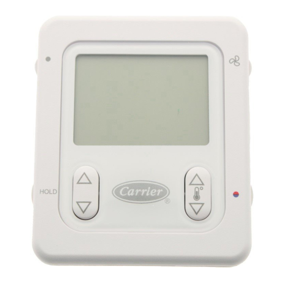
Infinity™ Smart Sensor for Zoning
Catalog No. 809-50013
Printed in U.S.A.
HOLD
HEIGHT (IN.)
WIDTH (IN.)
4
Infinity Smart Sensor
SYSTXCCSMS01
plied terminal block may be helpful in achieving proper wire
termination at the Damper Control Module.
A Smart Sensor may now be used to control Zone 1. In addition,
a Remote Room Sensor may also be used in the same zone. If a
Remote Room Sensor is applied in the same zone, the Remote
Room Sensor has temperature priority over the Smart Sensor.
INSTALLATION
Step 1—Select Smart Sensor Location
Sensor should be mounted:
• Approximately 5 ft. (1.5m) from floor.
• Close to center of zone, preferably on inside partitioning wall.
• On section of wall without pipes or ductwork.
• Where wiring can be routed to it within wall. Avoid running
directly next to other AC power.
Sensor should NOT be mounted:
• Close to a window, on outside wall, or next to a door leading
to the outside.
• Exposed to direct light and heat from a lamp, sun, fireplace, or
other temperature radiating object which may cause a false
reading.
• Close to or in direct airflow from supply registers and return-air
grilles.
• In areas with poor air circulation, such as behind a door or in
an alcove.
• Do not run wires next to AC power lines.
Form ZONESMS-1SI
A04147
DEPTH (IN.)
3-1/2
1
Pg 1
7-04
Replaces: NEW
Advertisement
Table of Contents

Related Manuals for Carrier Infinity Smart Sensor


Summary of Contents for Carrier Infinity Smart Sensor
- Page 1 INSTALLATION INTRODUCTION Step 1—Select Smart Sensor Location Carrier’s Infinity Smart Sensors are optional replacements for Sensor should be mounted: Remote Room Sensors used with Infinity zoning systems. They allow viewing and adjustment of temperatures from within the • Approximately 5 ft. (1.5m) from floor.
- Page 2 Step 2—Install Smart Sensor selected, press the FAN button to store the zone address and exit the setup menu. The Smart Sensor is ready to operate. CHANGING ZONE ADDRESS To change an existing zone address; enter the setup menu by ELECTRICAL SHOCK HAZARD Failure to follow this warning could result in personal injury pressing the FAN button for 10 seconds until the ZONE icon is...
- Page 3 displayed. Pressing the HOLD button again cancels the ″UNOC- VACATION CUPIED″ icon. When Unoccupied exits, the Smart Sensor will When the VACATION mode is activated from Zone Control (User return to the current operating mode. Interface), the Smart Sensor will display the ″VACATION″ icon in the lower left area of the LCD.
- Page 4 NOTE: * ABCD Connections are in Parallel with each other. Smart Sensors and Equipment may be connected in any combination. For easier troubleshooting, the installer may elect to use one terminal block for user interface and smart sensor connections, and the other for equipment connections. A B C D A B C D A B C D...
- Page 5 SMART SENSOR OPERATION The Infinity Smart Sensor allows control and changing of zone temperature setpoints. Continuous FAN selection is available; AUTO, LOW, MED, HIGH. Other features include viewing Outdoor Temperature and Indoor Relative Humidity. Infinity Smart Sensor Functions also include; HOLD and UNOCCUPIED settings.
- Page 8 Copyright 2004 CARRIER Corp. • 7310 W. Morris St. • Indianapolis, IN 46231 zonesms-1si Manufacturer reserves the right to discontinue, or change at any time, specifications or designs without notice and without incurring obligations. Book 1 1 4 4 Tab 3a 5a 2a 5a PC 101 Catalog No.
Need help?
Do you have a question about the Infinity Smart Sensor and is the answer not in the manual?
Questions and answers