Table of Contents
Advertisement
Quick Links
Montage- und Betriebsanleitung
Installation and operating instruction
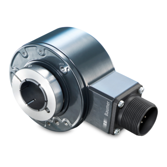
HS35
HS35 Serie
Series HS35
Merkmale
- Robustes Design bis
Schutzart IP 67
- Schockresistent bis 200 g
- Isolierhülse zum Schutz vor
Wellenströmen und Lager-
beschädigungen
- Breiter Betriebsspannungs-
bereich von 4,75...30 VDC
- Verschiedene Modelle
verfügbar
Features
- Rugged design up to IP 67
protection
- Shock resistant up to 200 g's
- Insulating sleeve to prevent
shaft currents from damaging
bearings
- Wide range supply voltage
4.75...30 VDC
- Various models available
Advertisement
Table of Contents

Related Manuals for Baumer HS35P


Summarization of Contents
General notes
Symbol guide
Explains symbols used in the manual for warnings and information.
Warranty
Details the 3-year warranty provided by Baumer for the product.
Disposal
Provides instructions for disposing of encoder components according to local regulations.
General safety instructions
Risk of Injury due to Rotating Shafts and Electric Current
Highlights risks of entanglement with rotating parts and electrical hazards during assembly.
Risk of Destruction due to Mechanical Overload
Warns against restricting movement, exceeding limits, or using force during installation.
Risk of Destruction due to Electrostatic Charge
Advises following ESD guidelines to protect sensitive electronic components from damage.
Explosion Risk
Prohibits use in areas with explosive or flammable materials due to potential sparking.
Preparation
Scope of delivery
Lists the items included in the product package.
Required resp. recommended for mounting
Details accessories and tools needed or recommended for product installation.
Required for electrical connection
Specifies cables and connectors needed for proper electrical setup.
Montage / Mounting
General installation instructions
Provides essential guidelines and precautions for the mounting process.
General view
Illustrates the encoder and mounting components for reference.
Step 1
First step in the mounting procedure, focusing on shaft preparation.
Step 2
Second step of mounting, involving fixing the tether arm to the encoder flange.
Dimensions
Dimension drawing
Provides a detailed drawing with all critical dimensions for the encoder.
Tolerances
Lists the specified tolerances for the encoder's hollow shaft and customer shaft.
Warranty
Loss of warranty
Outlines conditions under which the product warranty becomes void.
Maintenance
Maintenance
Recommends periodic bearing checks based on operating hours for longevity.
Electrical Connection
Terminal assignment HS35F & HS35P
Details the pin assignments for HS35F and HS35P models with MIL connectors.
Terminal assignment HS35S
Specifies the pin configuration for the HS35S model with its MIL connector.
Output signals HS35F/P
Illustrates the output signal waveforms (ABZ and ABZC) for HS35F/P models.
Output signals HS35S
Shows the differential output signals (A, B, Z) for HS35S models.
Dismounting
Step 1
First step for dismounting, involving removal of the protective cover.
Step 2
Second step of dismounting, focusing on loosening the clamp ring screw.
Step 3
Third step for dismounting, removing the customer-side fixing bolt.
Step 4
Final step for dismounting, carefully pulling the encoder off the motor shaft.
Accessories
Connectors and cables
Lists available connectors and cables for connecting the encoder.
Mounting accessories
Details accessories for mounting, such as tether arms and reducer inserts.
Technical Data
Mechanical data
Provides specifications on physical dimensions, protection ratings, and materials.
Electrical data
Details electrical parameters, output signals, and resolutions for different models.
Temperature diagram
Shows operating speed limits relative to ambient temperature and protection class.
Need help?
Do you have a question about the HS35P and is the answer not in the manual?
Questions and answers